
User-friendly printing press

A printing machine, a convenient technology, applied in the direction of printing machines, printing, general parts of printing machinery, etc., can solve problems such as increased cost, too thick powder layer, easy ink adhesion, etc., to reduce labor intensity, reduce usage, Guaranteed drying effect

Active Publication Date: 2017-01-04
慈溪市黎明彩印有限公司
View PDF8 Cites 4 Cited by
  • Summary
  • Abstract
  • Description
  • Claims
  • Application Information

AI Technical Summary

Problems solved by technology

In order to improve the printing efficiency, at present, the printed paper is usually wound together without air drying, which will cause the printed matter to adhere to the back of the printed matter, and the printing quality will also be affected. In order to solve this problem , the technician chooses to spray a layer of powder before the printed matter is wound, so that the surface of the printed matter is smooth and has no adhesion ability, but the thickness of the ink layer on the surface of some printed matter is different, and the existing technology adopts uniform powder spraying Thickness, resulting in some parts of the powder layer being too thick, which will have a certain impact on the printed matter, while some parts still have a certain adhesion ability due to the too thin powder layer, and the ink is easy to adhere to the contact with it during the winding process. On the paper, it will cause distortion of the printed matter and affect the effect of printing
During the production process, printing factories usually need to store a certain amount of printing paper raw materials, and printing paper has certain requirements for the storage environment. Small printing factories generally do not set up professional storage warehouses due to factors such as cost and space. , so that the printing paper may have excessive humidity or low humidity content, which will affect the printing effect
In order to solve this problem, a small dryer or humidifier is usually used for treatment before printing. However, since the general printing paper is in a roll structure, the inside is not easy to be dried or humidified, and the outside will be damaged due to excessive humidity. Drying or humidification leads to poor paper quality, resulting in unsatisfactory humidity regulation and low humidity regulation efficiency
For the replacement of ink, at present, the ink fountain is usually disassembled and cleaned, and then reinstalled after cleaning. Since the ink fountain is often disassembled, the probability of damage will increase. At the same time, since a printing machine has multiple ink fountains, this not only increases The labor intensity of workers will also affect the printing efficiency; in addition, the addition of ink is usually done manually after the ink fountain is installed, so it is difficult to accurately add the amount of ink, which affects the quality of printing , and when a variety of inks are required to be mixed, it is necessary to mix the inks first and then add them to the ink fountain, which will cause waste of ink residues and increase the cost of production; at the same time, after the existing ink addition technology adds the inks, the inks will be There will be no large movement, and the ink at the bottom will condense after a long time, which will affect the printing quality
Therefore, the existing technology has the disadvantages that the humidity of the printing paper cannot be adjusted in real time, the humidity adjustment effect of the printing paper is not ideal, the humidity adjustment efficiency is low, the thickness of the powder layer cannot be adjusted in real time during the powder spraying process, the powder spraying effect is not good, and the environment is polluted. , high labor intensity of workers, affecting the health of workers, high production costs, inconvenient cleaning of ink in the ink fountain, unsatisfactory printing efficiency, easy condensation of ink, inconvenient addition of ink, and poor printing quality, etc.

Method used


Image

  • User-friendly printing press
  • User-friendly printing press
  • User-friendly printing press

Examples


Embodiment Construction

[0024] The present invention will be further described below in conjunction with the accompanying drawings and examples, but not as a basis for limiting the present invention.

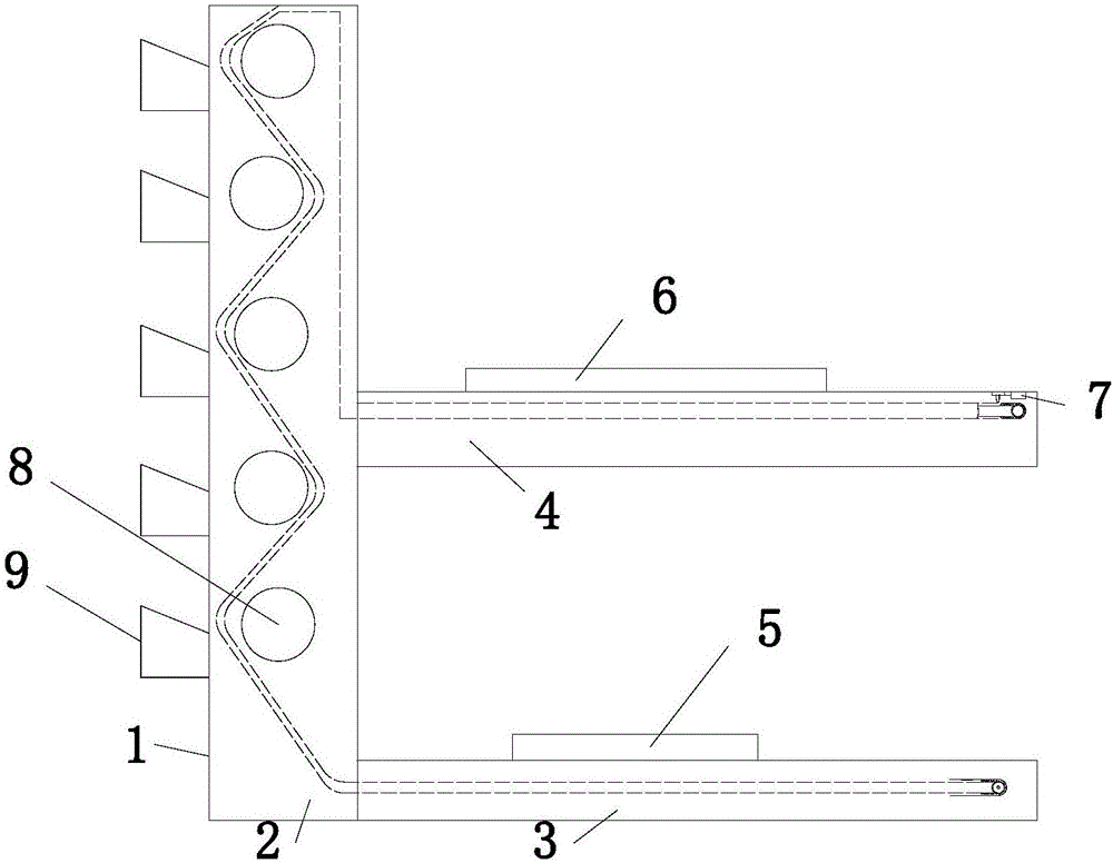
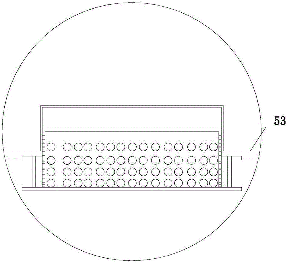
[0025] Example. A convenient printing machine, constituted as Figure 1 to Figure 8 Shown, comprise frame 1, and frame 1 comprises vertical section frame 2, and vertical section frame 2 lower end is provided with first horizontal section frame 3, and the middle part of vertical section frame 2 is provided with second horizontal section machine Frame 4, the first horizontal section frame 3 is provided with a paper processing device 5, the top of the second horizontal section frame 4 is provided with a powder spraying device 6, and the vertical section frame 2 is provided with multiple sets of printing rollers 8, the printing rollers 8 below is provided with ink fountain device 9 correspondingly; Described paper processing device 5, powder spraying device 6 and ink fountain device 9 are all connected wi...


PUM


Abstract

The invention discloses a user-friendly printing press. The printing press comprises a rack (1), wherein the rack (1) comprises a vertical rack (2); a first horizontal rack (3) is arranged at the lower end of the vertical rack (2); a second horizontal rack (4) is arranged at the middle part of the vertical rack (2); a paper processing device (5) is arranged on the first horizontal rack (3); a powder spray device (6) is arranged on the second horizontal rack (4); a printing roll (8) is arranged on the vertical rack (2); a duct device (9) is arranged below the printing roll (8); and the paper processing device (5), the powder spray device (6) and the duct device (9) are connected with a controller (7). The printing press has the characteristics of reducing the labor intensity of workers, improving the printing efficiency, improving the printing quality, facilitating the duct cleaning, preventing the ink from coagulation, adjusting the powder layer thickness in real time, reducing the production cost and adjusting the humidity of printing paper in real time.

Description

technical field [0001] The invention relates to a printing machine, in particular to a printing machine which is convenient to use. Background technique [0002] With the continuous development and progress of society, the demand for printing products is also expanding, and the content of printed products is becoming more and more abundant. Different printing materials require different printing plates and inks, and different inks have different adhesion capabilities and Adhesion ability is also different. In order to improve the printing efficiency, at present, the printed paper is usually wound together without air drying, which will cause the printed matter to adhere to the back of the printed matter, and the printing quality will also be affected. In order to solve this problem , the technician chooses to spray a layer of powder before the printed matter is wound, so that the surface of the printed matter is smooth and has no adhesion ability, but the thickness of the i...

Claims


Application Information

Patent Timeline
IPC IPC(8): B41F23/06B41F23/02B41F23/04B41F31/02B41F35/00
CPCB41F23/02B41F23/0403B41F23/06B41F31/02B41F35/00B41P2235/26
Inventor 虞建强虞东杰
Owner 慈溪市黎明彩印有限公司
Learn More