Baud-rate CDR circuit and method for low power applications

A clock data recovery, circuit technology, applied in the direction of automatic power control, electrical components, digital transmission systems, etc.

Active Publication Date: 2016-12-21
XILINX INC
View PDF4 Cites 6 Cited by
  • Summary
  • Abstract
  • Description
  • Claims
  • Application Information

AI Technical Summary

Problems solved by technology

Therefore, it is not optimal to maintain the data sampling clock centered between the zero crossings

Method used


Image

  • Baud-rate CDR circuit and method for low power applications
  • Baud-rate CDR circuit and method for low power applications
  • Baud-rate CDR circuit and method for low power applications

Examples


Embodiment Construction

[0016] Various features are described below with respect to the accompanying drawings. It should be noted that the drawings may or may not be drawn to scale and that elements having similar structure or function are represented by like reference numerals throughout the drawings. It should be noted that the drawings are only intended to facilitate the description of the features. It is not intended as a detailed description or as a limitation of the scope of the claimed invention. Furthermore, an illustrated embodiment need not have all of the aspects or advantages illustrated. Aspects or advantages described in connection with a particular embodiment are not necessarily limited to that embodiment, and may be practiced in any other embodiment although not shown or described in detail in any other embodiment.

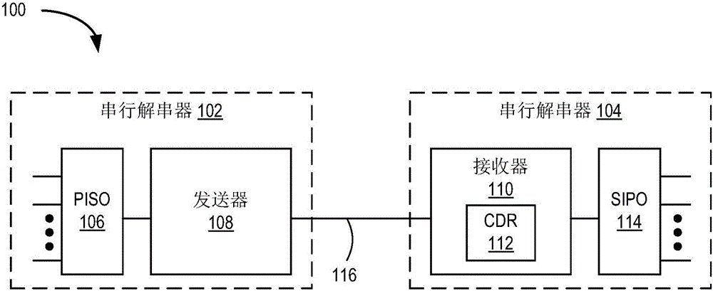
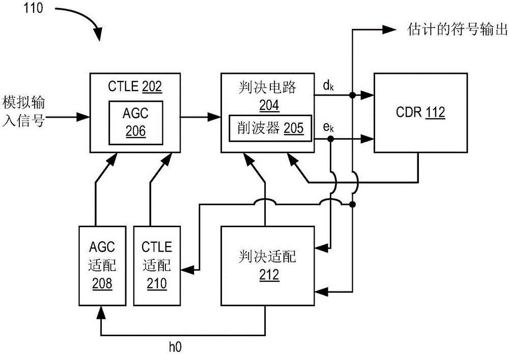
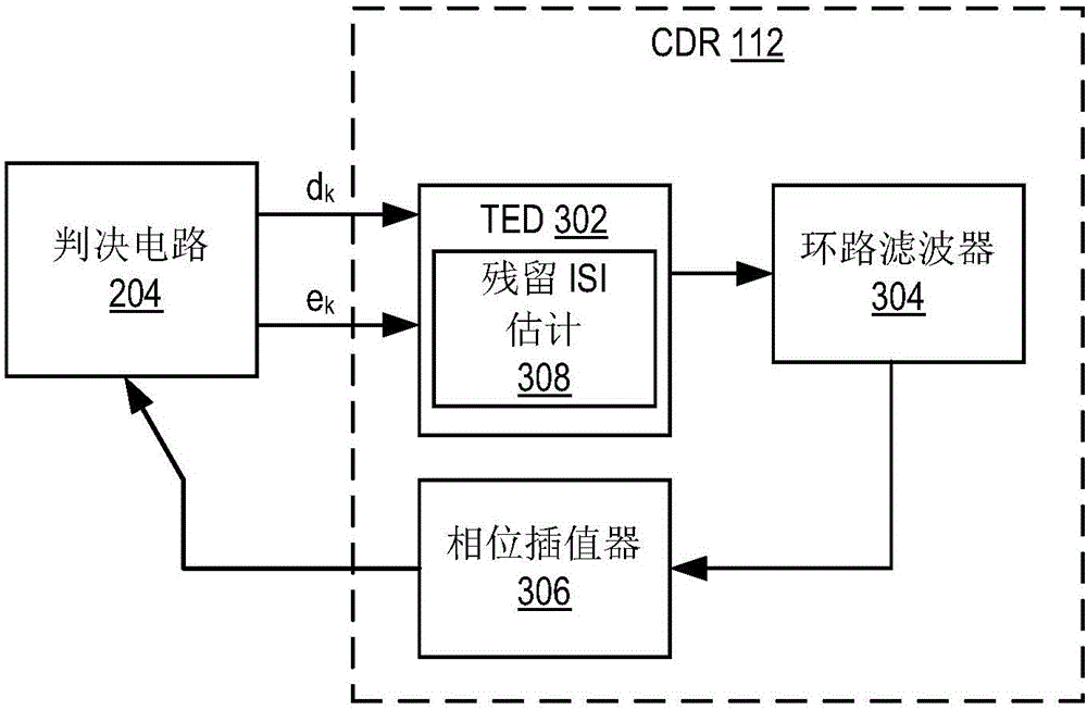
[0017] The techniques described here provide baud rate clock data recovery (CDR) for low power applications. The disclosed CDR circuit provides a robust CDR for use in...


PUM


Abstract

In an example, a clock data recovery (CDR) circuit for a receiver includes a timing error detector circuit, a loop filter, and a phase interpolator. The timing error detector circuit is coupled to receive, at a baud-rate, data samples and error samples for symbols received by the receiver. The timing error detector circuit is operable to generate both a timing error value and an estimated waveform value per symbol based on the data samples and the error samples. The loop filter is coupled to the timing error detector to receive timing error values. The phase interpolator is coupled to the loop filter to receive filtered timing error values, the phase interpolator operable to generate a control signal to adjust a sampling phase used to generate the data samples and the error samples.

Description

technical field [0001] Embodiments of the present disclosure relate generally to electronic circuits and, more particularly, to baud rate clock data recovery (CDR) circuits for low power applications. Background technique [0002] Clock data recovery (CDR) is an important block in receiver systems for high-speed serial communications. The CDR module generates the correct sampling clock phase for data recovery. The quality of high-speed serial communication links is very sensitive to the sampling clock phase, especially in the presence of jitter and noise [0003] An existing CDR is edge-sampled CDR (edge-sampled CDR). Edge-sampling CDRs oversample the analog input waveform to generate the correct data sampling clock and recover the transmitted data. Edge sampling CDR assumes that data is sampled near the center between zero crossings. The resulting oversampled system consumes more clock power than a system operating at the symbol rate (also known as the baud rate). Furt...

Claims


Application Information

Patent Timeline
Patent Type & Authority Applications(China)
IPC IPC(8): H03L7/081H04L7/04
CPCH03L7/081H04L7/04H04L7/0025H04L7/0062H04L7/0087
Inventor 张稼丰张洪涛吴昭颖张琨永廖宇
Owner XILINX INC
Why Eureka
Try Eureka