Electric vehicle voltage converting circuit

A voltage conversion circuit and voltage converter technology are applied in the direction of output power conversion devices, electrical components, and electrical variables to adjust, which can solve problems such as energy waste and battery power waste, and achieve the effect of reducing risks.

Inactive Publication Date: 2016-12-21
浙江和睿半导体科技有限公司
View PDF10 Cites 1 Cited by
  • Summary
  • Abstract
  • Description
  • Claims
  • Application Information

AI Technical Summary

Problems solved by technology

[0003] The power supply of an electric vehicle is generally a storage battery. Now the voltage specification of the storage battery is 72V. It needs to be converted to 12V for the headlights of the electric vehicle through a certain circuit. This voltage conversion can be realized in the prior art, but it is not There is no function to effectively detect the working status of the headlights. For special cases, such as: during the day, it is not necessary to turn on the headlights. Sometimes people forget to turn off the headlights after using them, so that the headlights remain on during the day. open, resulting in a waste of energy, especially a waste of battery power

Method used


Image

  • Electric vehicle voltage converting circuit
  • Electric vehicle voltage converting circuit
  • Electric vehicle voltage converting circuit

Examples


Embodiment 1

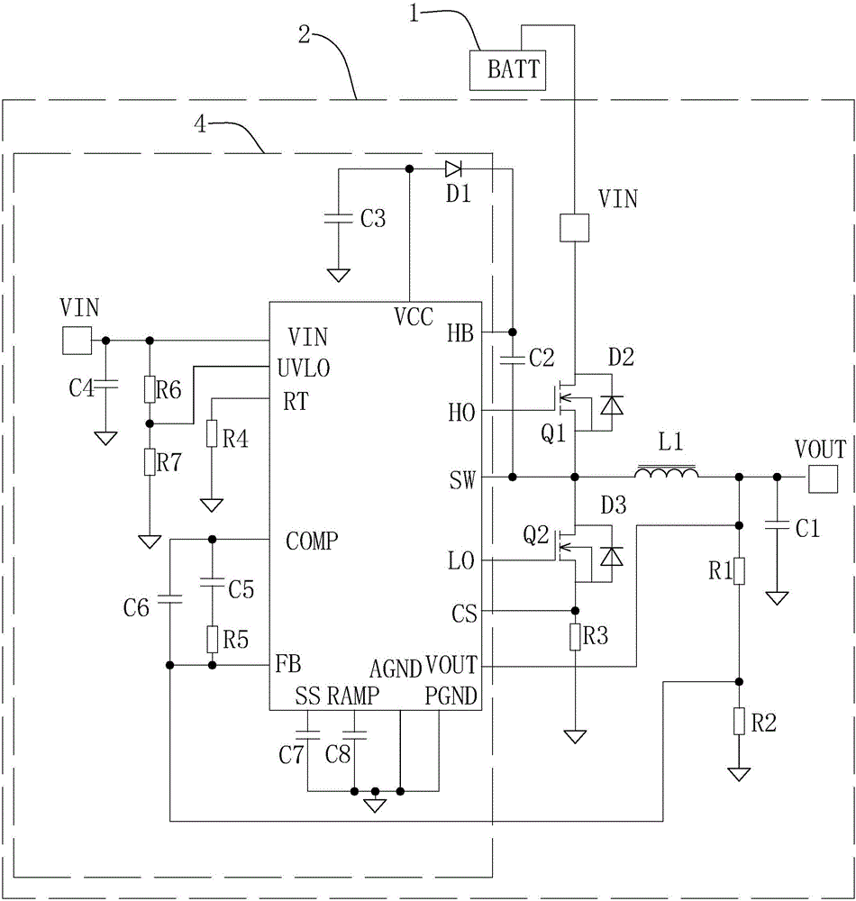
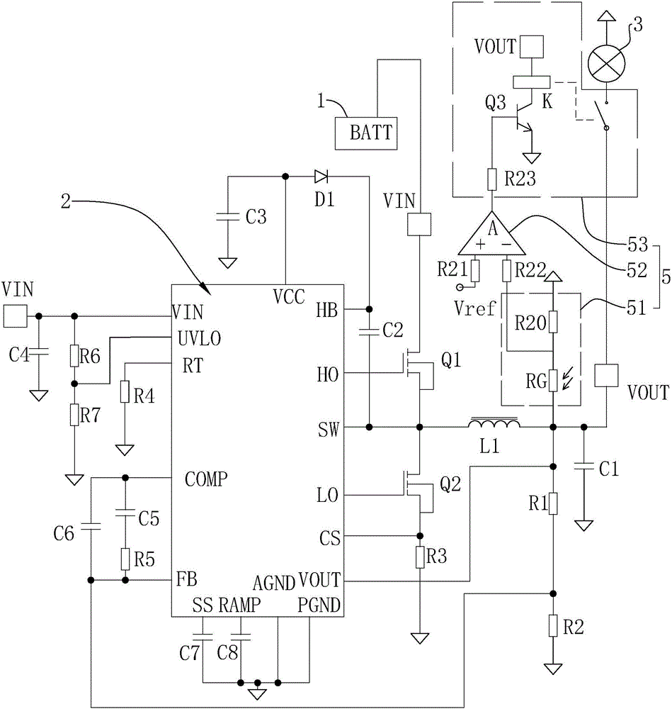
[0042] Embodiment 1: a kind of electric vehicle voltage conversion circuit, such as figure 1 As shown, including battery 1, voltage converter 2, and headlight 3 connected in sequence (see figure 2 ), the voltage converter 2 includes an input terminal VIN, a first MOS transistor Q1 , a second MOS transistor Q2 , an inductor L1 , an output terminal VOUT, and a PWM output module 4 .

[0043] The PWM output module 4 includes an IC chip whose model is LM5117. This IC chip has HO pins, SW pins, LO pins, CS pins, VCC pins, VIN pins, UVLO pins, RT pins, and COMP pins. Pin, FB pin, SS pin, RAMP pin, AGND pin, PGND pin, etc. The VIN pin is connected to the input terminal VIN, one end of the capacitor C4, one end of the resistor R6, the other end of the capacitor C4 is grounded, the other end of the resistor R6 is connected to the one end of the resistor R7, the UVLO pin, the other end of the resistor R7 is grounded, and the RT pin is grounded through the resistor R4 , the COMP pin is...

Embodiment 2

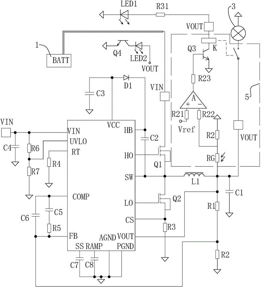
[0049] Embodiment 2: as image 3 As shown, the cable between the storage battery 1 and the input terminal is provided with an indicating circuit, and the indicating circuit includes a light-emitting diode LED1, a phototransistor Q4, and an indicator LED2; the anode of the light-emitting diode LED1 is connected to the output terminal VOUT, and the cathode is grounded; the phototransistor Q4 emits The pole is grounded, the collector is connected to the cathode of the indicator LED2, and the anode of the indicator LED2 is connected to the output terminal VOUT.

[0050] Working process: The cables connected to the power supply of the existing storage battery 1 are prone to loosening, and the long-term vibration during the driving of the electric vehicle is more likely to make the cables loose, which is likely to cause potential safety hazards. Through this circuit, you can design by checking whether the cable blocks the light-emitting diode LED1 and whether it blocks the photosens...


PUM


Abstract

The invention discloses an electric vehicle voltage converting circuit and is aimed at providing the electric vehicle voltage converting circuit capable of automatically controlling electric power transmission of a power source and reducing electricity waste. Key points of a technical solution of the electric vehicle voltage converting circuit are that the electric vehicle voltage converting circuit comprises a storage battery, a voltage converter and a head lamp that are orderly connected; the electric vehicle voltage converting circuit is characterized in that the voltage converter comprises an input end VIN, a first MOS transistor, a second MOS transistor, an electric inductor, an output end VOUT and a PWM output module; the PWM output module comprises an HO lead pin, an SW lead pin, an LO lead pin and a CS lead pin; the HO lead pin is connected with a grid electrode of the first MOS transistor, and the LO lead pin is connected with a grid electrode of the second MOS transistor; the SW lead pin is connected with a source electrode of the first MOS transistor, a drain electrode of the second MOS transistor and one end of the inductor; a drain electrode of the first MOS transistor is connected with the input end VIN, a source electrode of the second MOS transistor is connected with the CS lead pin and a grounding end, the other end of the inductor is connected with the output end VOUT, the output end VOUT is also connected with an optical switch module, the optical switch module is coupled to a position between the head lamp and the output end VOUT, and on-off of the head lamp can be controlled according to ambient light rays.

Description

technical field [0001] The invention relates to the technical field of electric vehicle control, in particular to an electric vehicle voltage conversion circuit. Background technique [0002] At present, the Chinese patent with the notification number CN205430056U discloses a voltage conversion device for electric vehicles, including a PWM control circuit, a switch tube, a voltage feedback circuit, a current sampling circuit, and a power supply circuit. The power supply circuit is used to supply power to the PWM control circuit. The output terminal of the PWM control circuit is connected to the gate of the switch tube through the MOS tube drive circuit, the drain of the switch tube is connected to the power input terminal of the voltage converter, and the source of the switch tube is connected to the power output of the voltage converter An energy storage inductance is arranged between the ends, the input end of the voltage feedback circuit is connected to the power output e...

Claims


Application Information

Patent Timeline
Patent Type & Authority Applications(China)
IPC IPC(8): H02M3/156
CPCH02M3/156
Inventor 郑石磊刘卫卫杨秋冬郑振军
Owner 浙江和睿半导体科技有限公司
Why Eureka
Try Eureka