
Magnetic shielding structure applied to ultrahigh voltage autotransformer clamp

An autotransformer and magnetic shielding technology, which is applied in transformers, fixed transformers, magnetic field/electric field shielding, etc., can solve the problems of reducing loss, local overheating, hysteresis loss, eddy current loss, etc., to reduce additional loss, reduce accident rate, Effect of improving electrical conversion efficiency

Inactive Publication Date: 2016-12-21
WOLONG ELECTRIC GRP CO LTD +1
View PDF8 Cites 4 Cited by
  • Summary
  • Abstract
  • Description
  • Claims
  • Application Information

AI Technical Summary

Problems solved by technology

Since the leakage flux density of this type of transformer accounts for a large proportion of the main flux density, and the leakage flux passes through the steel clamp, eddy current loss and hysteresis loss will be generated, which will further cause the clamp to heat up.
Generally, products of 220KV and below use low magnetic permeability or non-magnetic steel plates to make relevant clamps, limbs, etc., but the leakage flux density between the inner and outer windings of ultra-high voltage autotransformers is as high as 30% to 40% of the main flux density , the loss caused by it accounts for 30%~50% of the basic copper loss, and the usual method is not enough to effectively reduce the loss and eliminate the hidden danger of local overheating

Method used


Image

  • Magnetic shielding structure applied to ultrahigh voltage autotransformer clamp
  • Magnetic shielding structure applied to ultrahigh voltage autotransformer clamp
  • Magnetic shielding structure applied to ultrahigh voltage autotransformer clamp

Examples


Embodiment Construction

[0021] The technical solution of the present invention will be further described in detail below in conjunction with the accompanying drawings.

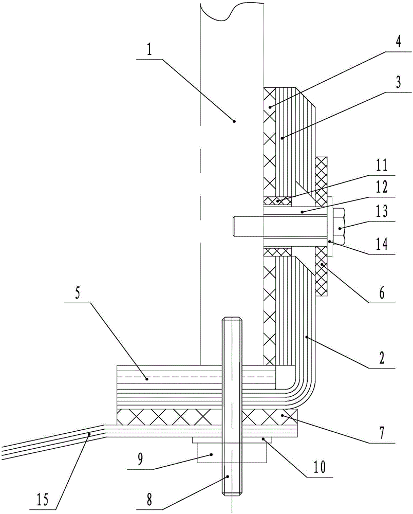
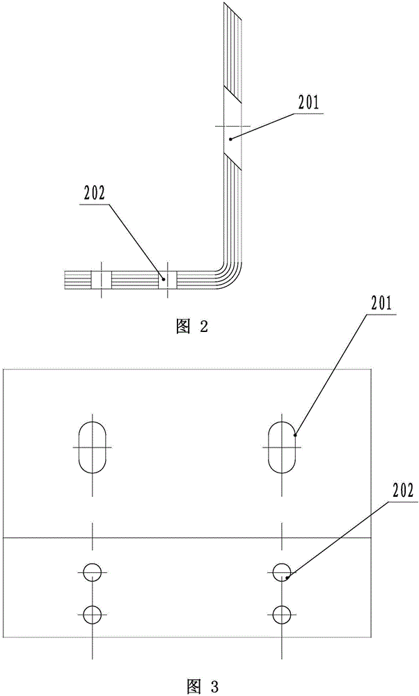
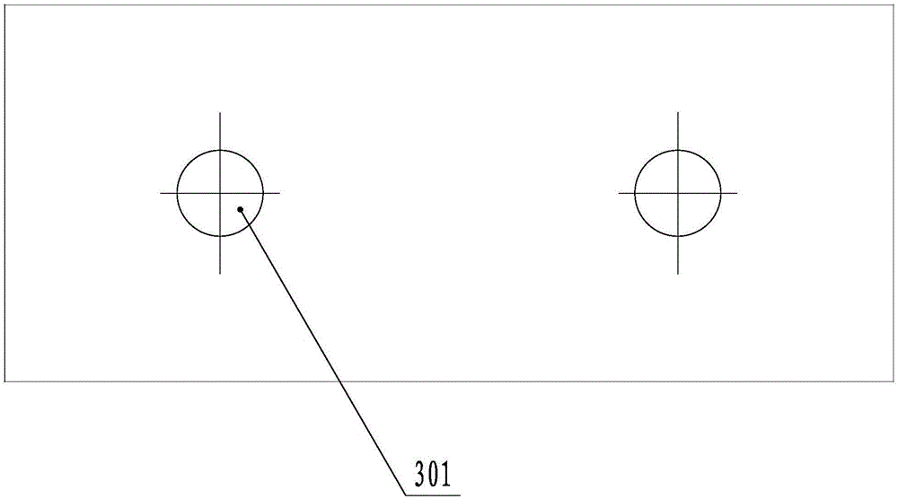
[0022] Such as Figure 1-4 As shown, the present invention includes a bent magnetic shield 2, a first inner insulating backing plate 4, a fastener connecting the bent magnetic shielding 2 and the first inner insulating backing plate 4 to the clip 1, and the bent magnetic shield 2. The cross-section is "L", and the bending part has a circular arc transition; the bending magnetic shielding part 2 is arranged at the outer end of the clamping part 1. By installing an "L"-shaped bent magnetic shield 2 on the outer end of the clip 1 with a relatively high leakage flux density, the leakage flux is reduced from entering the non-magnetic clip 1, and the leakage flux can be effectively reduced additional loss.

[0023] In order to better reduce the leakage magnetic flux into the non-magnetic clip 1, it also includes a direct magnetic shield ...


PUM

PropertyMeasurementUnit
thicknessaaaaaaaaaa
heightaaaaaaaaaa

Abstract

The invention provides a magnetic shielding structure applied to an ultrahigh voltage autotransformer clamp and relates to the magnetic shielding structure. The magnetic flux leakage density between an inner winding and an outer winding of the ultrahigh voltage autotransformer is high; and the loss cannot be effectively reduced and the hidden danger of local overheating cannot be effectively eliminated by use of a usual method. The magnetic shielding structure comprises a bent magnetic shielding part, a first insulating base plate and a fastener of connecting the bent magnetic shielding part and the first insulating base plate to the clamp; the cross section of the bent magnetic shielding part is L-shaped and the bent part is in circular arc transition; and the bent magnetic shielding part is arranged at the outer end part of the clamp. The L-shaped bent magnetic shielding part is added to the outer end part of the clamp with relatively high leakage flux density, so that leakage flux entering a non-magnetic clamp is reduced and the additional loss generated by the leakage flux can be effectively reduced.

Description

technical field [0001] The invention relates to a magnetic shielding structure, in particular to a magnetic shielding structure applied to an ultra-high voltage autotransformer clip. Background technique [0002] The magnetic shield is composed of multi-layer laminated silicon steel sheets with good magnetic permeability. According to the different shielding parts, it is usually divided into fuel tank magnetic shielding, clip magnetic shielding, etc. Magnetic shielding is generally used in high-voltage, high-capacity transformers. Since the magnetic leakage density of this type of transformer accounts for a large proportion of the main magnetic flux density, eddy current loss and hysteresis loss will be generated when the leakage magnetic flux passes through the steel clamp, which will further cause the clamp to heat up. Generally, products of 220KV and below use low magnetic permeability or non-magnetic steel plates to make relevant clamps, limbs, etc., but the leakage fl...

Claims


Application Information

Patent Timeline
Patent Type & Authority Applications(China)
IPC IPC(8): H01F27/36H01F30/02H05K9/00
CPCH01F27/36H01F30/02H05K9/0018
Inventor 柏广洲于春梅孙长山魏喜柱王伟
Owner WOLONG ELECTRIC GRP CO LTD
Learn More