A cavernous double-layer containment vessel for an underground nuclear power plant

A double-layer containment and containment technology, applied in the field of nuclear power, can solve the problems of reducing the seismic performance of the containment, expanding the accident hazards, insufficient cooling water, etc., so as to improve the ability to resist external events, improve the seismic performance, and increase the pressure bearing capacity. effect of ability

Active Publication Date: 2018-01-23
CHANGJIANG SURVEY PLANNING DESIGN & RES
View PDF8 Cites 0 Cited by
  • Summary
  • Abstract
  • Description
  • Claims
  • Application Information

AI Technical Summary

Problems solved by technology

In this open heat dissipation method, the water used as the cooling source will be consumed due to continuous evaporation, which may eventually lead to insufficient cooling water in the later stage of the accident.
The design of the water tank on the top of the containment also reduces the overall seismic performance of the containment to a certain extent
In addition, the interior of the containment of this design is separated from the outside atmosphere by only a layer of steel containment. If the containment is damaged in an accident, the radioactive material in the containment will be sucked through the chimney effect through the breach. The effect accelerates the leakage to the external environment and expands the accident hazard
This kind of risk basically exists in the existing double-layer containment, such as the Chinese patent: ambient air cooling system and passive containment with this system (application number: CN201310576926.0; Chinese patent) only set the deflector at the air inlet , the containment itself has no substantial change; Chinese patent: large-capacity completely passive containment cooling system (application number: CN200910226276.0) only optimizes the design of the cooling water tank, and realizes dynamic control of cooling power through flow adjustment; the above inventions all exist Potential risk of expanding accident hazards

Method used


Image

  • A cavernous double-layer containment vessel for an underground nuclear power plant

Examples


Embodiment Construction

[0021] The present invention will be described in further detail below in conjunction with the accompanying drawings and embodiments, but these embodiments should not be construed as limiting the present invention.

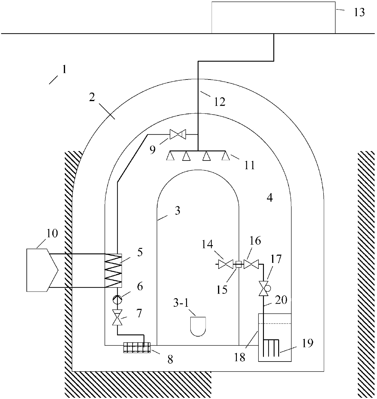
[0022] The present invention is an underground nuclear power plant cavern type double-layer containment such as figure 1 As shown, it includes a surface pool 13 located on the ground and a containment vessel located in the underground rock formation 1 . The containment vessel is provided with an outer rock mass reconstruction layer 2 and an inner steel containment vessel 3 sequentially from the outside to the inside, and the nuclear power plant pressure vessel 3-1 is placed in the inner steel containment vessel 3 . An annular containment interlayer space 4 is formed between the outer rock mass reconstruction layer 2 and the inner steel containment vessel 3 , and a closed circulation heat exchange system is arranged in the containment interlayer space 4 . The clos...


PUM


Abstract

The invention discloses a cavern-type double-layer containment for an underground nuclear power plant, which includes a ground pool on the ground and a containment in an underground rock layer. The containment is sequentially arranged with an outer layer of rock mass reconstruction layer and an inner layer of steel The containment shell, the outer rock mass reconstruction layer and the inner steel containment shell form an annular containment interlayer space, and a closed cycle heat exchange system is installed in the containment interlayer space, including the spray at the bottom of the containment interlayer space Water collection and filtration wells, spray water collection and filtration wells pass through the first check valve, digitally controlled pressurized pump, containment heat exchanger, second check valve and the containment spray port above the inner steel containment in sequence The containment spray port is also connected to the ground pool through the ground connection pipe. The invention conducts the heat of the containment through a long-term closed cooling cycle, and realizes the absolute isolation of the containment from the external environment through the underground rock formation, avoiding the release of a large amount of radioactivity to the environment due to the damage of the containment.

Description

technical field [0001] The invention relates to nuclear power technology, in particular to a cavern-type double-layer containment vessel of an underground nuclear power plant. Background technique [0002] As the last defense barrier of the ground nuclear power plant, the containment shell is used to contain airborne radioactive releases in severe accidents and prevent a large amount of radioactive substances from being released to the environment. Underground nuclear power plants put nuclear islands and other nuclear-related plants underground, which greatly improves the overall safety of nuclear power plants and provides new ideas for the safe development of nuclear power in my country. [0003] In severe accidents, the pressure inside the containment increases with the temperature, and an atmospheric environment of high temperature, high pressure, high humidity and high radiation is formed inside the containment. At this time, in order to prevent the failure of the conta...

Claims


Application Information

Patent Timeline
Patent Type & Authority Patents(China)
IPC IPC(8): G21C15/14G21C15/18
CPCG21C15/14G21C15/18Y02E30/30
Inventor 赵鑫刘海波张涛喻飞苏毅金乾汪建曾杰陈玉梅鱼维娜
Owner CHANGJIANG SURVEY PLANNING DESIGN & RES
Why Eureka
Try Eureka