Thermal energy dynamic system of oil field exhaust gas based on cyclic condensation of working medium

A technology of working fluid circulation and power system, which is applied to machines/engines, steam engines, mechanical equipment, etc., and can solve the problem of poor heat collection effect of heat collectors, low efficiency of turbine work conversion, and unstable working fluid gasification temperature, etc. To achieve the effect of improving work conversion efficiency, improving heat energy conversion efficiency, and increasing heat energy conversion efficiency

Inactive Publication Date: 2016-12-21
郭远军
View PDF0 Cites 0 Cited by
  • Summary
  • Abstract
  • Description
  • Claims
  • Application Information

AI Technical Summary

Problems solved by technology

[0007] However, the common problems of existing thermal power generation equipment are: a. The temperature at the exhaust port of the turbine is relatively high, resulting in high pressure at the exhaust port, and the work conversion efficiency of the turbine is low; b. The heat displacement of the condensing device is relatively large , the waste of heat energy is large, the condensation speed through natural condensation is slow, and the active condensation method (fan air cooling or liquid pump water cooling) requires additional power consumption; c. The temperature requirements for high-temperature heat sources are high, generally above 200 ° C, and The thermal energy conversion efficiency is low, and the thermal energy conversion efficiency is generally 15% to 35%; d. Gasification heat absorption is slow, and the output power of the thermal energy machine is relatively small; e. The heat collection effect of the heat collection device is not good, and the external waste heat absorption rate is small , f. The gasification temperature of the working fluid is unstable, the condensation effect of the working fluid is not good, and the working fluid is easy to deteriorate or appear impurities

Method used


Image

  • Thermal energy dynamic system of oil field exhaust gas based on cyclic condensation of working medium
  • Thermal energy dynamic system of oil field exhaust gas based on cyclic condensation of working medium
  • Thermal energy dynamic system of oil field exhaust gas based on cyclic condensation of working medium

Examples


Embodiment 1

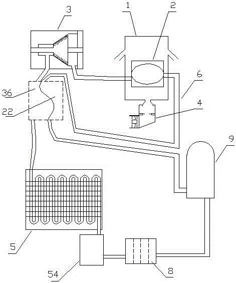
[0081] Embodiment one (such as figure 1 Shown): An oilfield waste gas thermal energy power system based on working medium circulation condensation, including a heat collector 1, a gasification device 2, a turbine 3, an oilfield waste gas combustion device 4, a condensation device 5, a circulation pipeline 6, and a circulation medium 7 And the one-way hydraulic pump 9, the gasification device 2, the turbine 3, the condensing device 5 and the one-way hydraulic pump 9 realize the circulation communication through the circulation pipeline 6 in sequence. Outside the gasification device 2, it is used for gasification heating of the working fluid in the gasification device 2;

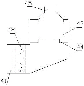
[0082] (Such as figure 2 As shown) the oil field waste gas combustion device 4 includes a waste gas inlet 41, an oil field waste gas induced fan 42, a waste gas combustion chamber 43, a continuous igniter 44 and a hot gas discharge pipe 45, an air inlet 41, a waste gas combustion chamber 43 and a hot gas dis...

Embodiment 2

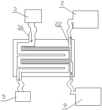
[0095] Embodiment two (such as Figure 6 Shown): The difference from Embodiment 1 is that the heat collecting device 1 includes an upper cover 11 and a lower cover 12, a heating port 13 is provided in the middle of the lower cover 12, and the upper cover 11 and the lower cover 12 are respectively located on the upper and lower sides. Between 11 and the lower cover 12 is a heat collecting chamber 14, two layers of upper cover protruding rings 111 are distributed on the lower part of the upper cover 11 of the heat collecting device 1, and two layers of lower cover protruding rings 121 are distributed on the upper part of the lower cover 12 of the heat collecting device 1, The protruding ring 111 of the upper cover and the protruding ring 121 of the lower cover are staggered.

[0096] By conducting experiments on the thermal energy power system of oil field waste gas based on working medium circulation condensation in the above-mentioned embodiment 2, the oil field waste gas is ...

Embodiment 3

[0097] Embodiment three (such as Figure 7 Shown): The difference from Embodiment 1 is that the lower part of the upper cover 11 of the heat collecting device 1 is provided with a three-layer upper cover protruding ring 111, and the upper part of the lower cover 12 of the heat collecting device 1 is distributed with a three-layer lower cover protruding ring 121 , the upper cover protruding ring 111 and the lower cover protruding ring 121 are staggered.

[0098] By conducting experiments on the thermal energy power system of oil field waste gas based on working medium circulation condensation in the above-mentioned embodiment three, the oil field waste gas is introduced into the oil field waste gas combustion device 4, and the combustion temperatures in the oil field waste gas combustion device 4 are respectively 120°C, 150°C, and 200°C. °C, 250 °C, 300 °C, 400 °C, the flow rate of the working medium in the circulation pipe is adjusted according to the operation stability of t...


PUM


Abstract

The invention discloses a thermal energy dynamic system of oil field exhaust gas based on cyclic condensation of working medium comprising a gasification device, a turbine, a condensation device and a one-way hydraulic pump which are successively cycled and communicated through a circulating pipeline; circulating work medium is contained in the circulating pipeline; a thermal-arrest device which is installed outside the gasification device is communicated with an oil field exhaust gas burner comprising an exhaust gas inlet, an oil field exhaust gas induced draught fan, an exhaust gas combustion chamber, a continuous fire guider and a hot gas discharge pipe; the gasification device comprises a gasification chamber and a preheating chamber; an exhaust port of the turbine is provided with a pre-condensing chamber which is in touch with the preheating chamber in parallel. The thermal energy dynamic system of oil field exhaust gas based on cyclic condensation of working medium can accelerate the condensation, improve the efficiency of the turbine, reduce the heat expelled outside, and thereby enhance the heat energy conversion efficiency.

Description

technical field [0001] The invention belongs to the field of energy utilization equipment, in particular to an oil field waste gas heat energy power system based on working medium circulation condensation. Background technique [0002] Energy is an important material basis for the survival and development of human society. Throughout the history of the development of human society, every major progress of human civilization is accompanied by the improvement and replacement of energy. The development and utilization of energy has greatly promoted the development of the world economy and human society. [0003] However, with the continuous development and consumption of energy, non-renewable energy sources such as petroleum, coal mines, and natural gas are gradually reduced, and energy conservation and recycling are gradually being valued. The basic content of my country's current energy strategy is: adhere to the priority of conservation, based on domestic, diversified deve...

Claims


Application Information

Patent Timeline
Patent Type & Authority Applications(China)
IPC IPC(8): F01K11/02F01K13/00
CPCF01K11/02F01K13/00F01K13/006
Inventor 郭远军
Owner 郭远军
Why Eureka
Try Eureka