
Motor direct-driven transmission device of door lock and intelligent door lock

A transmission device and intelligent door lock technology, which is applied to non-mechanical transmission-operated locks, building locks, lock casings, etc., can solve the problems of reducing the service life of intelligent locks, low mechanical transmission efficiency, and large footprint, achieving Low noise, compact structure, the effect of improving life

Inactive Publication Date: 2016-12-14
WUXI AT FEELING TECH CO LTD
View PDF6 Cites 15 Cited by
  • Summary
  • Abstract
  • Description
  • Claims
  • Application Information

AI Technical Summary

Problems solved by technology

The existing electronic lock mainly adopts the electronic lock body with a built-in clutch mechanism. The modification needs to replace the original mechanical lock body with the electronic lock body, and the modification process is complicated.
[0003] The existing method to solve this kind of problem is to install a clutch separately outside the lock body, so that the installation process of the lock body is simple and convenient. Usually, the clutch function is realized by pressing the pin of the clutch, but because the pin pressing device can move as a whole, the stability is poor , there are defects such as easy jamming, poor anti-theft and anti-prying performance
[0004] In the prior art, the smart door locks that automatically unlock and lock mostly use a large number of gears and linkage mechanical structures, and have defects such as low mechanical transmission efficiency, large space occupation, easy wear and tear, and reduced service life of smart locks.

Method used


Image

  • Motor direct-driven transmission device of door lock and intelligent door lock
  • Motor direct-driven transmission device of door lock and intelligent door lock
  • Motor direct-driven transmission device of door lock and intelligent door lock

Examples


Embodiment 1

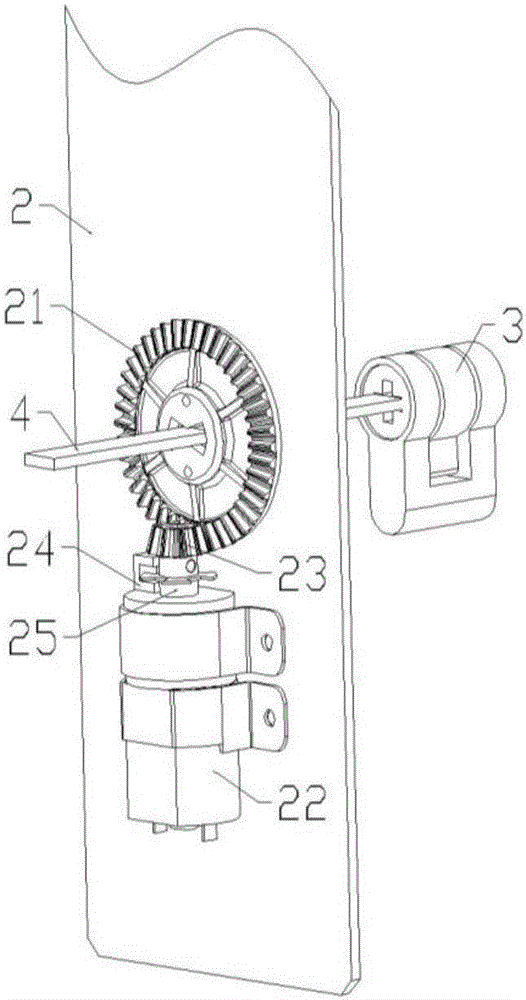
[0041] Such as Figure 1~3 As shown, a motor direct drive transmission device at least includes a door inner panel 1 , a bottom plate 2 , a lock cylinder 3 , and a dial 4 .

[0042] The door inner panel 1 is provided with an unlock knob 11 . The door inner panel 1 is installed on the inner side of the door during installation.

[0043] The bottom plate 2 is provided with a driving bevel gear 21 , a deceleration motor 22 , a motor bevel gear 23 , a photoelectric switch 24 , a grating encoding disc 25 , a buffer pad 26 and a locking cover 27 . The driving bevel gear 21 meshes with the motor bevel gear 23 , and the reduction motor 22 is connected and matched with the motor bevel gear 23 through its power output end. Specifically, the motor bevel gear 23 and the driving bevel gear 21 are a pair of bevel gears meshing with each other, and the reduction motor 22 transmits the power stage torque to the motor bevel gear 23 through its power output end, and the motor bevel gear 23 E...

Embodiment 2

[0046] An intelligent door lock based on a motor direct drive transmission device includes the motor direct drive transmission device of Embodiment 1. It also includes an outer panel, a mechanical handle 12, a power supply module 13, an intelligent door lock MCU 14, and a wireless communication module 15.

[0047] The mechanical handle 12 is arranged on the inner panel of the door. The outer panel is provided with a touch keyboard, a biometric identification module and an outer door handle. The touch keyboard, the biometric identification module, and the outside handle are wired with the smart door lock MCU. The touch keyboard is on the surface of the outer panel and is used for inputting passwords.

[0048] The biometric identification module is arranged inside the outer panel, and its detection sensor is arranged outside the outer panel; the biometric identification module is a combination of fingerprint identification and iris identification.

[0049] The outside handle of...

Embodiment 3

[0053] An intelligent door lock based on a motor direct drive transmission device includes the motor direct drive transmission device of Embodiment 1, and also includes an outer panel, a power supply module 13, an intelligent door lock MCU 14, a wireless communication module 15, and a door closing detection module.

[0054] The outer panel is provided with a touch keyboard, a biometric identification module and an outer door handle. The touch keyboard, the biometric identification module, and the outside handle are wired with the smart door lock MCU. The touch keyboard is on the surface of the outer panel and is used for inputting passwords. The biometric identification module is arranged inside the outer panel, and its detection sensor is arranged outside the outer panel; the biometric identification module is a combination of fingerprint identification and iris identification. The outside handle of the door is separated from the dial, and there is no mechanical connection b...


PUM


Abstract

The invention discloses a motor direct-driven transmission device of a door lock and an intelligent door lock. The motor direct-driven transmission device mainly comprises an inner door panel, a bottom plate, a lock core, a shifting strip and components like an unlocking rotary knob, a driving bevel gear, a gear motor, a motor bevel gear, an optoelectronic switch, an optical grating coding disc, a buffer cushion and a locking cover. According to the motor direct-driven transmission device, the lock core is driven to rotate through the gear motor, automatic locking and unlocking functions of an electronic door lock are achieved through utilizing a traditional mechanical lock body, and the motor direct-driven transmission device has the advantages that the changing and mounting are easy, the cost is low, the operation is stable, reliable, safe and convenient, the device is abrasion resistant, the noise is low, and the service life is long, integrates convenience of an intelligent lock and safety and reliability of a mechanical lock, and has wide application prospect in the field of intelligent door locks.

Description

technical field [0001] The invention relates to a motor direct drive transmission device, in particular to an intelligent door lock based on the motor direct drive transmission device and an automatic locking and unlocking method thereof. Background technique [0002] With the advancement of electronic technology, more and more electronic locks, which are safer and more convenient than mechanical locks, have entered thousands of households. The existing electronic lock mainly adopts an electronic lock body with a built-in clutch mechanism. Refitting needs to replace the original mechanical lock body with an electronic lock body, and the refitting process is complicated. [0003] The existing method to solve this kind of problem is to install a clutch separately outside the lock body, so that the installation process of the lock body is simple and convenient. Usually, the clutch function is realized by pressing the pin of the clutch, but because the pin pressing device can mo...

Claims


Application Information

Patent Timeline
Patent Type & Authority Applications(China)
IPC IPC(8): E05B47/00E05B49/00E05B9/00E05B17/22E05B17/00E05B15/00E05B3/00G07C9/00
CPCE05B47/0012E05B3/00E05B9/002E05B15/00E05B17/0045E05B17/22E05B49/00E05B2047/002E05B2047/0067G07C9/00563G07C9/00817
Inventor 张畯钦徐公云
Owner WUXI AT FEELING TECH CO LTD
Learn More