Adjusting and filtering type canning equipment with drip-proof device
A technology for adjusting filtration and anti-drip, applied in packaging, liquid bottling, transportation and packaging, etc., can solve the problem of reducing the accuracy and service life of the filling head, the residual liquid flowing back into the filling machine, and the high maintenance and maintenance costs. problem, to achieve the effect of good anti-drip effect, reduced manpower and simple structure
- Summary
- Abstract
- Description
- Claims
- Application Information
AI Technical Summary
Problems solved by technology
Method used
Image
Examples
Embodiment 1
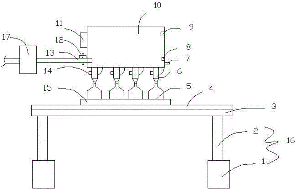
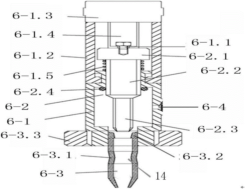
[0022] Such as Figures 1 to 3 As shown, the present embodiment provides an adjustable filtering type canning equipment with an anti-drip device, including an oil storage tank 10, which is characterized in that the bottom of the oil storage tank 10 is provided with several filling heads 6, each The filling heads 6 all include a filling head housing 6-1, a cut-off rod 6-2, a needle 6-3 and a liquid inlet 6-4, and the upper side of the filling head housing 6-1 is fixedly connected with an installation Seat 6-1.2, the installation seat 6-1.2 is fixed with an installation cylinder 6-1.3, the top of the installation seat 6-1.2 is fixed on the bottom of the oil storage tank 10, and the lower side of the filling head housing 6-1 is connected with a needle 6-1. 3. The bottom of the filling head housing 6-1 is provided with a needle reinforcement mounting part 6-3.3, and the cylinder rod 6-1.4 and the cut-off rod 6-2 are connected by a screw 6-1.6. The extruding part 6-3.1 is a rubber...
Embodiment 2
[0024] This embodiment has been further optimized on the basis of Embodiment 1, specifically:
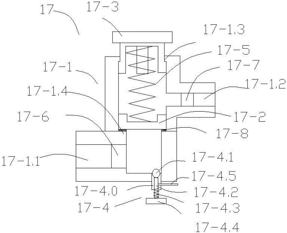
[0025] The contact surfaces of the rotary regulating valve 17-3 and the fastening port 17-1.3 are respectively provided with mutually compatible threads; the valve body 17-1 is also provided with a stop groove 17-1.4, and the valve core 17-2 It is arranged on the stop groove 17-1.4 inside the valve body 17-1; the first compression spring 17-5 is arranged between the valve core 17-2 and the rotary regulating valve 17-3.
[0026] A sealing ring 17-8 is provided between the contact surface of the valve core 17-2 and the stop groove 17-1.4.
[0027] The cut-off rod 6-2 includes a top seat 6-2.1 arranged at the top, a sealing shaft part 6-2.2 arranged at the middle and a cut-off part 6-2.3 arranged at the bottom; the lower end of the cut-off part 6-2.3 is connected to The needles 6-3 abut against each other; the sealing shaft part 6-2.2 passes through the upper opening of the filling he...
Embodiment 3
[0029] The present embodiment is further optimized on the basis of embodiment 1 or 2, specifically as follows:
[0030] Each filling head 6 is respectively equipped with a filling valve 14, the lower part of the oil storage tank 10 is provided with an oil replenishment sensor 8, and the upper part is provided with an oil overflow sensor 9, and one side of the oil storage tank 10 is also provided with A control box 11 is provided, the input ends of the control box 11 are respectively connected with the oil replenishment sensor 8 and the oil overflow sensor 9 , and the output end of the control box 11 is connected with the solenoid valve 12 .
[0031] One side of the oil storage tank 10 is provided with a control switch 7 for controlling the filling valve 14 , and the control switch 7 is electrically connected to the filling valve 14 .
[0032] The one-way unloading port 17-4 is arranged at the bottom of the valve body 17-1, including an unloading passage 17-4.0, an unloading va...
PUM
 Abstract
Description
Claims
Application Information
 - R&D Engineer
- R&D Manager
- IP Professional
- Industry Leading Data Capabilities
- Powerful AI technology
- Patent DNA Extraction
Browse by: Latest US Patents, China's latest patents, Technical Efficacy Thesaurus, Application Domain, Technology Topic, Popular Technical Reports.
© 2024 PatSnap. All rights reserved.Legal|Privacy policy|Modern Slavery Act Transparency Statement|Sitemap|About US| Contact US: help@patsnap.com


