
Packaging tray for liquid crystal display panel and extensible and retractable unit pieces constituting packaging tray

A liquid crystal panel, retractable technology, applied in the field of retractable monomers, can solve the problems of increased difficulty in placing sheets in automatic packaging equipment, affecting packaging quality, and inaccurate placement of sheets, so as to avoid glass damage and damage , The effect of low manufacturing cost

Active Publication Date: 2016-12-14
WUHAN CHINA STAR OPTOELECTRONICS TECH CO LTD
View PDF9 Cites 1 Cited by
  • Summary
  • Abstract
  • Description
  • Claims
  • Application Information

AI Technical Summary

Problems solved by technology

[0005] The purpose of the present invention is to provide a packaging tray for liquid crystal panels and the telescopic monomers that make up the tray, to solve the problem of increased difficulty in placing sheets in automated packaging equipment due to the narrow assembly gap between the tray and the panel The position is not accurate, resulting in the occurrence of fragments in the next process, which seriously affects the packaging quality.

Method used


Image

  • Packaging tray for liquid crystal display panel and extensible and retractable unit pieces constituting packaging tray
  • Packaging tray for liquid crystal display panel and extensible and retractable unit pieces constituting packaging tray
  • Packaging tray for liquid crystal display panel and extensible and retractable unit pieces constituting packaging tray

Examples


specific Embodiment approach 1

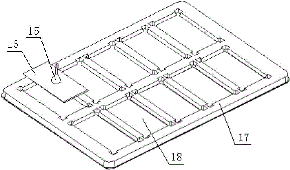
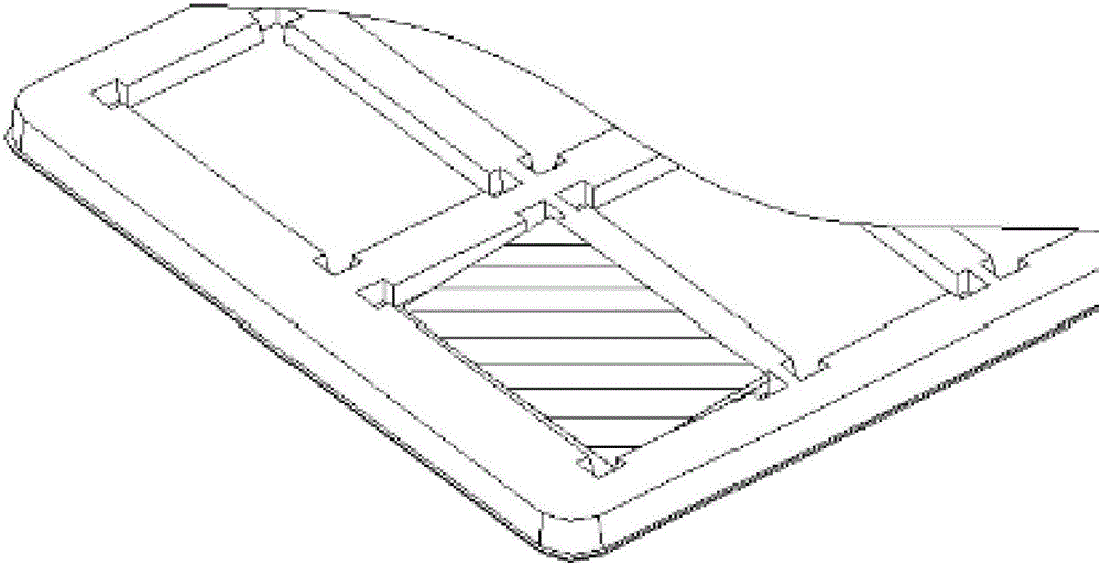
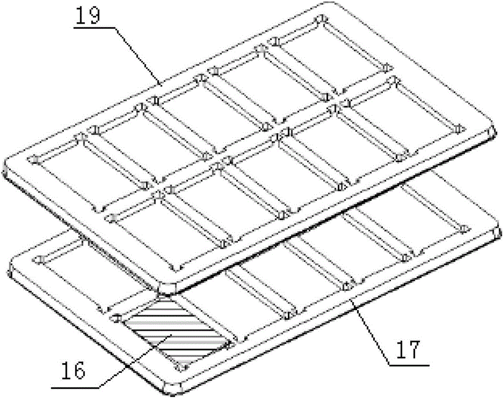
[0032] Specific implementation mode one: combine figure 1 , figure 2 , image 3 , Figure 4 , Figure 5 , Figure 6 , Figure 7 , Figure 8 and Figure 9 Describe this embodiment, this embodiment includes several telescopic monomers 1, several telescopic monomers 1 are arranged in a rectangular array, and several telescopic monomers 1 are fixedly connected in turn to form a pallet body as a whole, each telescopic The monomer 1 includes a base plate 2 and four edges 3, the base plate 2 is arranged horizontally and its top view shape is a quadrangle, and the four edges 3 are arranged in sequence along the periphery of the base plate 2 and outward in a direction perpendicular to the base plate 2 protruding, and each edge 3 is fixedly connected to an edge of the bottom plate 2, each edge 3 is a telescopic edge, and adjacent telescopic monomers 1 are spaced apart by the edge 3, and each telescopic One glass substrate 4 can be accommodated in the single body 1 .

[0033] I...

specific Embodiment approach 2

[0035] Embodiment 2: This embodiment is a further limitation of Embodiment 1. In this embodiment, the four edges 3 in each telescopic monomer 1 include two transverse edges 5 and two longitudinal edges 6, The transverse edge 5 is arranged along the length direction of its base plate 2, and the longitudinal edge 6 is arranged along the width direction of its base plate 2. The structures of the transverse edge 5 and the longitudinal edge 6 are identical, and each transverse edge 5 includes a first The elastic middle section 5-1 and two first fixed end portions 5-2, the two ends of the first elastic middle section 5-1 are respectively fixedly connected with a first fixed end portion 5-2; each longitudinal edge 6 includes The second elastic middle section 6-1 and two second fixed end portions 6-2, two ends of the second elastic middle section 6-1 are respectively fixedly connected with a second fixed end portion 6-2.

specific Embodiment approach 3

[0036] Specific Embodiment 3: This embodiment is a further limitation of Specific Embodiment 2. In this embodiment, the bottom plate 2 in each telescopic monomer 1 is a telescopic plate body, and the bottom plate 2 in each telescopic monomer 1 includes The transverse elastic slats 7, the longitudinal elastic slats 8 and the four fixing plates 9, the transverse elastic slats 7, the longitudinal elastic slats 8 and the four fixing plates 9 are on the same plane and are sequentially fixed and connected as one. The longitudinal directions of the transverse elastic slats 7 and the longitudinal elastic slats 8 are perpendicular to each other, and the two ends of the transverse elastic slats 7 in the longitudinal direction and the two second elastic middle sections 6- 1 is fixedly connected, the two ends of the length direction of the longitudinal elastic slats 8 are fixedly connected with the two first elastic middle sections 5-1 in the telescopic monomer 1, the transverse elastic sl...


PUM


Abstract

The invention provides a packaging tray for a liquid crystal display panel and extensible and retractable unit pieces constituting the packaging tray. The packaging tray for the liquid crystal display panel and the extensible and retractable unit pieces constituting the packaging tray solve the problems that because the assembly gap between a tray and the panel is narrow, the difficulty degree for automatic packaging equipment to place the panel is increased, the placed panel is aligned inaccurately, and the panel is damaged on the next procedure, and the packaging quality is influenced seriously. The packaging tray for the liquid crystal display panel comprises the extensible and retractable unit pieces. The extensible and retractable unit pieces are arranged in a rectangular array and are sequentially and fixedly connected to be integrated and form a tray body. Each extensible and retractable unit piece comprises a four base plate and four edges. Each base plate is horizontally arranged, and the shape of the base plate is a quadrangle when people look down the base plate. The four edges of each extensible and retractable unit piece are sequentially arranged around the periphery of the corresponding base plate and protrude outwards in the direction perpendicular to the corresponding base plate. Each edge is fixedly connected to one brim of the corresponding base plate and is an extensible and retractable edge. The adjacent extensible and retractable unit pieces are spaced through the edges. The inner portion of each extensible and retractable unit piece can contain a glass substrate.

Description

technical field [0001] The invention specifically relates to a packaging tray for liquid crystal panels and telescopic monomers that make up the tray. Background technique [0002] The LCD panel can determine the brightness, contrast, color, and viewing angle of the LCD display to a large extent. The development speed of the LCD panel is very fast. The LCD panel part is closely related to the LCD display. Its output, advantages and disadvantages, and market Various factors such as the environment are related to the quality, price and market trend of the LCD itself, because about 80% of the cost of an LCD is concentrated on the panel. [0003] Products such as panels for smartphones and tablet computers will continue to be the main driving force for the growth of small and medium-sized panel shipments and output value in recent years; among them, smartphone panels account for 80% of the output value. After entering the era of eyeballs, smart terminal devices combined with cl...

Claims


Application Information

Patent Timeline
Patent Type & Authority Applications(China)
IPC IPC(8): B65D19/24B65D19/38
CPCB65D19/0036B65D19/38B65D2519/00034B65D2519/00069B65D2519/00268B65D2519/00288B65D2519/00318B65D2519/00975
Inventor 岳亮
Owner WUHAN CHINA STAR OPTOELECTRONICS TECH CO LTD
Learn More