
Signal modulating device

A technology for signal modulation and signal integration, applied in the field of signal modulation devices, can solve the problems of modulator dynamic range attenuation, reducing filtering ability, blocking and other problems, and achieve the effect of eliminating peaks

Inactive Publication Date: 2016-12-07
MEDIATEK INC
View PDF3 Cites 1 Cited by
  • Summary
  • Abstract
  • Description
  • Claims
  • Application Information

AI Technical Summary

Problems solved by technology

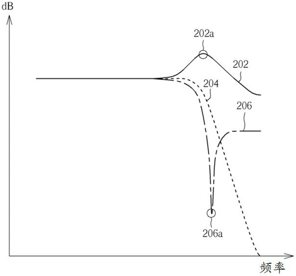
However, the feed-forward topology exhibits large out-of-band peaking in the signal transfer function (STF), which will be a problem in wireless applications with strong interference / blocking
More specifically, when out-of-band interferers are present, out-of-band peaks may reduce the filtering capability provided by the baseband filter or IF filter as well as lead to attenuation of the dynamic range of the modulator
At the same time, large out-of-band signals can potentially overload the input of the quantizer and lead to an unstable modulator

Method used


Image

  • Signal modulating device
  • Signal modulating device
  • Signal modulating device

Examples


Embodiment Construction

[0013] The following descriptions are preferred embodiments for implementing the present invention. The following examples are only used to illustrate the technical characteristics of the present invention, and are not intended to limit the scope of the present invention. Certain terms are used throughout the specification and claims that follow to refer to particular elements. It should be understood by those skilled in the art that manufacturers may use different terms to refer to the same element. The specification and claims do not use the difference in name as the way to distinguish components, but the difference in function of the components as the basis for the difference. The terms "element", "system" and "apparatus" used in the present invention may be a computer-related entity, where the computer may be hardware, software, or a combination of hardware and software. The terms "comprising" and "including" mentioned in the following description and claims are open ter...


PUM


Abstract

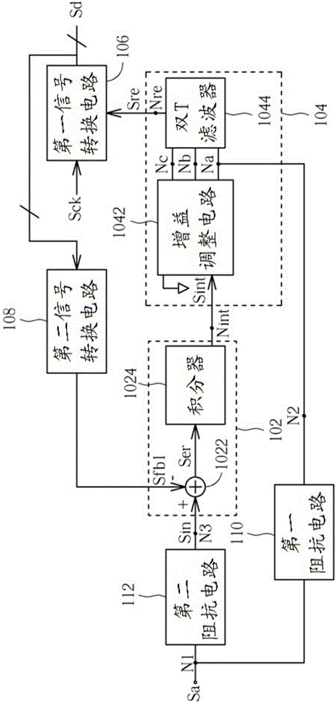
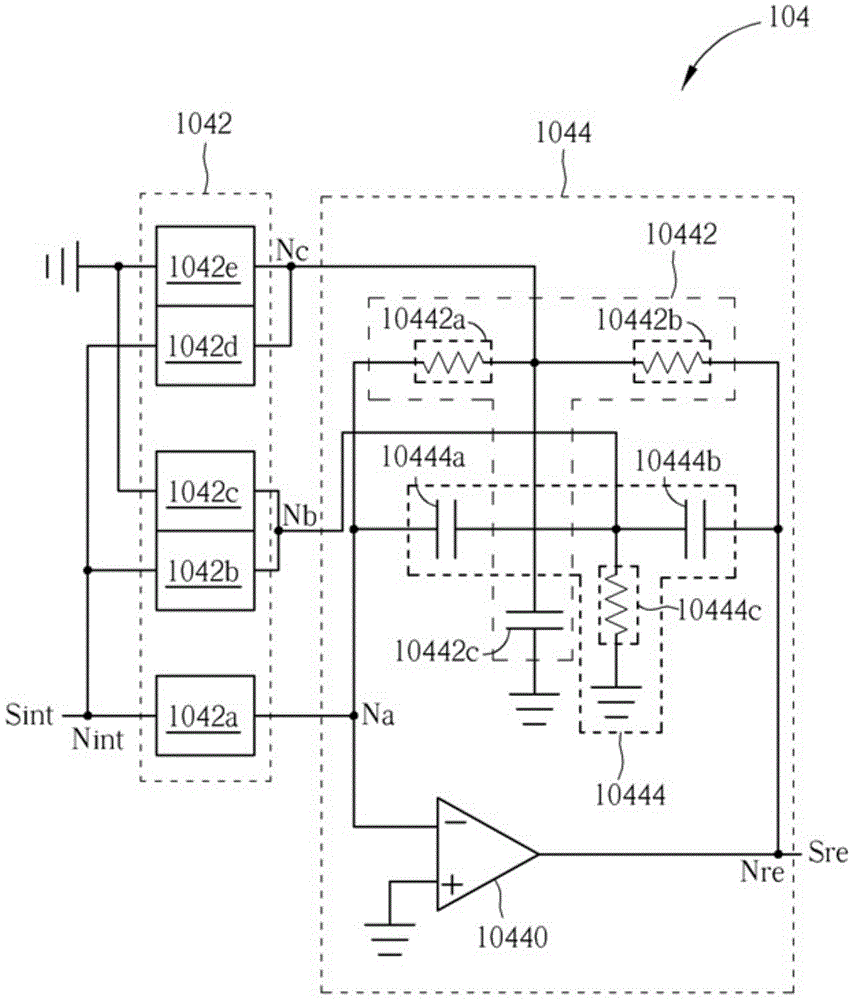
The invention provides a signal modulating device which includes: an integrating circuit arranged to generate an integrated signal according to a scaled analog signal and a first feedback signal; a resonating circuit arranged to generate a resonating signal according to the integrated signal; a first signal converting circuit arranged to convert the resonating signal into a digital output signal; a second signal converting circuit arranged to convert the digital output signal into the first feedback signal; a first impedance circuit having a first terminal receiving an analog signal and a second terminal coupled to the resonating circuit for altering the location of zeros in the forward-path transfer function and consequently shaping the signal transfer function (STF) of the signal modulating device; and a second impedance circuit having a first terminal receiving the analog signal and a second terminal coupled to the integrating circuit for generating the scaled analog signal. By using the signal modulating device, the peaking in the STF can be effectively reduced or eliminated.

Description

technical field [0001] The present invention relates to signal modulation technology, and more particularly, to a signal modulation device. Background technique [0002] Compared with the feedback topology, the feed-forward topology (feed-forward topology) has the advantages of lower internal signal amplitude and fewer feedback digital-to-analog elements. Therefore, the continuous-time Σ-Δ modulator (continuous-time sigma-delta modulator, CT-SDM) is often chosen to implement in a feed-forward topology. However, the feed-forward topology exhibits large out-of-band peaking in the signal transfer function (STF), which will be a problem in wireless applications with strong interference / blocking. More specifically, when out-of-band interferers are present, out-of-band peaks may reduce the filtering capability provided by the baseband filter or IF filter and lead to attenuation of the dynamic range of the modulator. At the same time, large out-of-band signals could potentially o...

Claims


Application Information

Patent Timeline
IPC IPC(8): H03M3/00
Inventor 洪立翰黄彦筌王麒云楼志宏
Owner MEDIATEK INC
Learn More