Method for eliminating peak value during running of single phase direct-current brushless motor
A brushless DC motor, a technology in operation, applied to emergency protection circuit devices, electrical components, circuit devices and other directions for limiting overcurrent/overvoltage, and can solve problems such as the inability of single-phase brushless DC motors to eliminate peaks
Active Publication Date: 2011-06-15
DONGGUAN JUNKAI ELECTRONICS
View PDF3 Cites 0 Cited by
- Summary
- Abstract
- Description
- Claims
- Application Information
AI Technical Summary
Problems solved by technology
Method used
View moreImage
Smart ImageViewing Examples


Examples
Embodiment Construction
Login to View More PUM
 Abstract
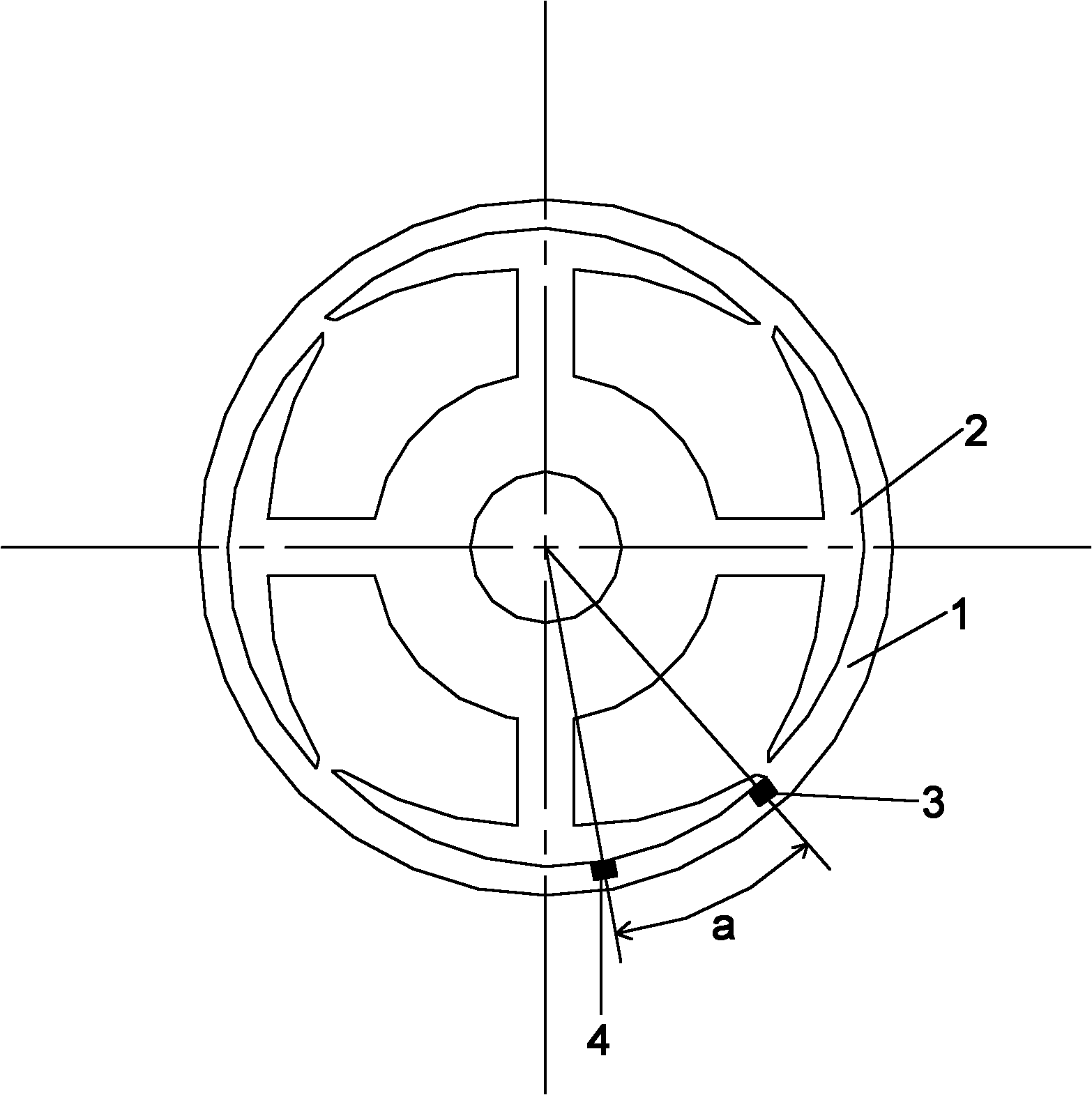
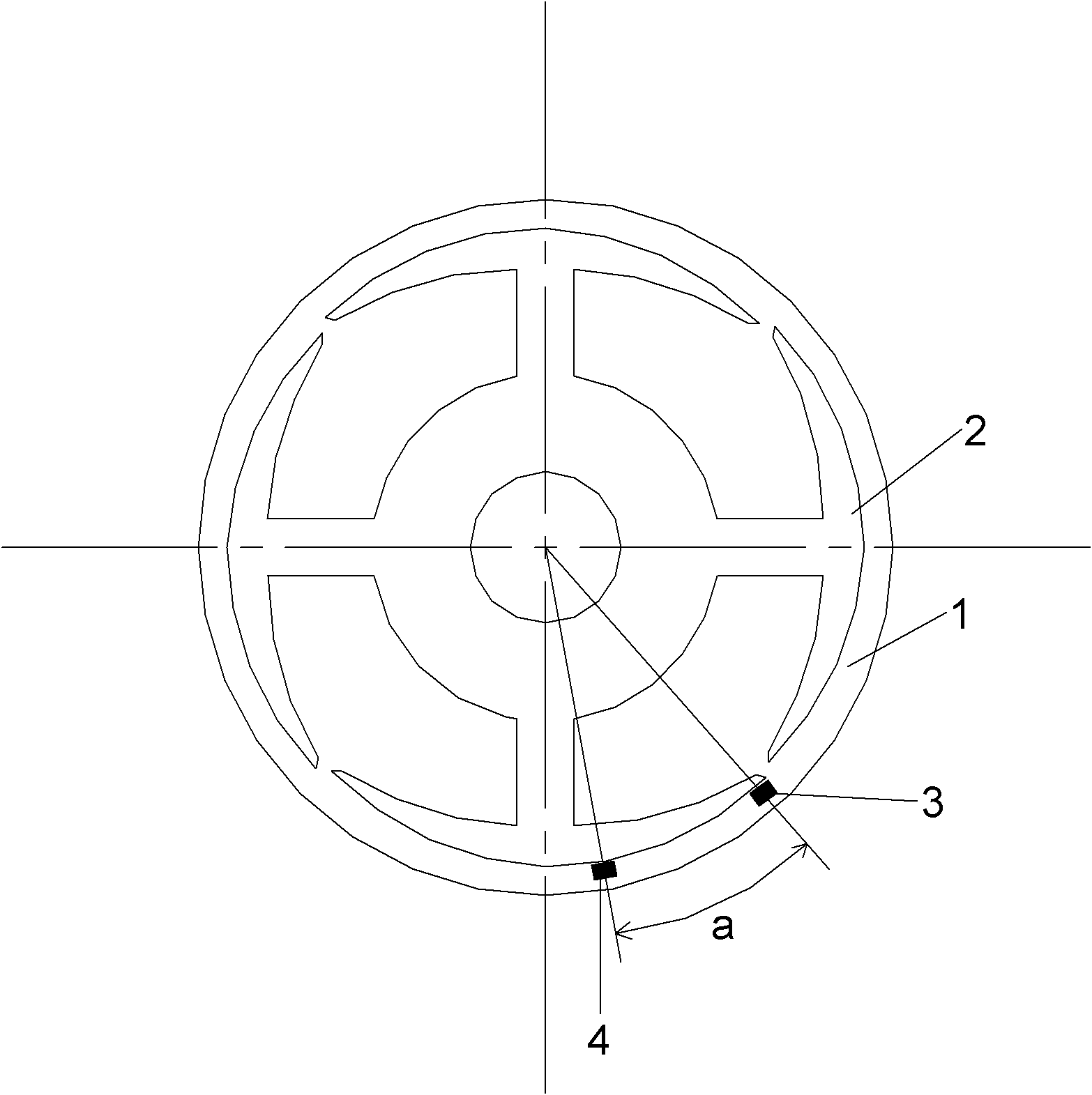
The invention belongs to the technical field of single phase direct-current brushless motors and in particular relates to a method for eliminating a peak value during the running of a single phase direct-current brushless motor. The method comprises the following steps of: arranging two HALL ICs (Integrated Circuits) at the periphery of a stator silicon steel sheet on a motor circuit board, wherein one HALL IC is positioned at the upmost end of the stator silicon steel sheet, and the other HALL IC is positioned at the second high-end of the stator silicon steel sheet, therefore, an angle difference is formed between the two HALL ICs; and releasing coil energy by utilizing the delay time formed by the angle difference and through discharge circuits arranged on the circuit board and connected with the two HALL ICs so as to eliminate the peak value in the single phase direct-current brushless motor. After the technical scheme is adopted, the delay time is formed through the angle difference between the two HALL ICs, and the coil energy is first released at the instant of magnetic pole switching by utilizing the DELAY time, therefore, the peak value during the running of the single phase direct-current brushless motor is eliminated, the interference noise is reduced, and meanwhile, the start shaking problem can also be solved.
Description
A method for eliminating peaks in single-phase DC brushless motor operation Technical field: The invention belongs to the technical field of single-phase direct current brushless motors, and particularly relates to a method for eliminating peaks in the operation of single-phase direct current brushless motors. Background technique: The existing single-phase DC brushless motor usually adopts a single HALLIC, which cannot eliminate the peak value (ie Vpk value) at both ends of the online package generated by the high-speed and high-power single-phase brushless DC motor during operation. When the brushless motor runs at high speed, the peak value generated on the wire package cannot be released in time to form a peak value, and the components (ie power tubes) that drive the wire package have the maximum voltage that they can withstand, so the components will be damaged. . Invention content: The purpose of the present invention is to solve the problem that the existing sin...
Claims
Login to View More Application Information
Patent Timeline
 IPC IPC(8): H02H9/04H02P6/10
Inventor 郑早平
Owner DONGGUAN JUNKAI ELECTRONICS
Features
- R&D
- Intellectual Property
- Life Sciences
- Materials
- Tech Scout
- Unparalleled Data Quality
- Higher Quality Content
- 60% Fewer Hallucinations
Learn More Browse by: Latest US Patents, China's latest patents, Technical Efficacy Thesaurus, Application Domain, Technology Topic, Popular Technical Reports.
© 2025 PatSnap. All rights reserved.Legal|Privacy policy|Modern Slavery Act Transparency Statement|Sitemap|About US| Contact US: help@patsnap.com