
Output filter applied to open winding transformer type dual inverters

An output filter, transformer type technology, applied in the field of new energy grid-connected power generation, can solve the problems of large filter inductance, small output voltage harmonics of dual inverter topology, and high cost, and achieves reduction in inductance and reduction. Filter cost, effect of high harmonic suppression capability

Inactive Publication Date: 2016-12-07
HEFEI UNIV OF TECH
View PDF6 Cites 2 Cited by
  • Summary
  • Abstract
  • Description
  • Claims
  • Application Information

AI Technical Summary

Problems solved by technology

This kind of filter can make the output voltage harmonics of the two inverters cancel each other through the filter inductor and the shared filter capacitor. The coupling between the circuit and the harmonic bypass branch will affect the high-frequency filtering effect, the required filter inductance is still large, and there is still room for improvement
[0010] To sum up, the existing technical solutions are difficult to take into account at the same time: ① retain the advantage of the dual-inverter topology output voltage harmonics is small; ② use high-order filters to provide higher harmonic attenuation capabilities
This makes the filter require a larger inductance to meet the corresponding filtering requirements, and the cost is higher

Method used


Image

  • Output filter applied to open winding transformer type dual inverters
  • Output filter applied to open winding transformer type dual inverters
  • Output filter applied to open winding transformer type dual inverters

Examples


Embodiment 1

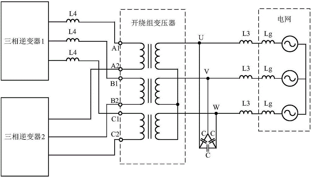
[0025] figure 1 Shown is an output filter structure applied to an open-winding transformer-type dual inverter disclosed in the first embodiment of the present invention. The A-phase winding of the open-winding transformer is provided with a primary-side three-phase terminal A1 and a disassembled-side three-phase terminal A2, the B-phase winding is provided with a primary side three-phase terminal B1 and a disassembly side three-phase terminal B2, and the C-phase winding is provided with a primary side three-phase terminal C1 and a disassembly side three-phase terminal C2; the output filter includes The three-phase inverter 1 and the three-phase inverter 2 on the primary side of the winding transformer, the output filter also includes a three-phase filter reactance L3 and a three-phase filter capacitor C arranged on the secondary side of the open-winding transformer; One end of the reactor L3 is connected to the secondary side of the three-phase winding of the open-winding transf...

Embodiment 2

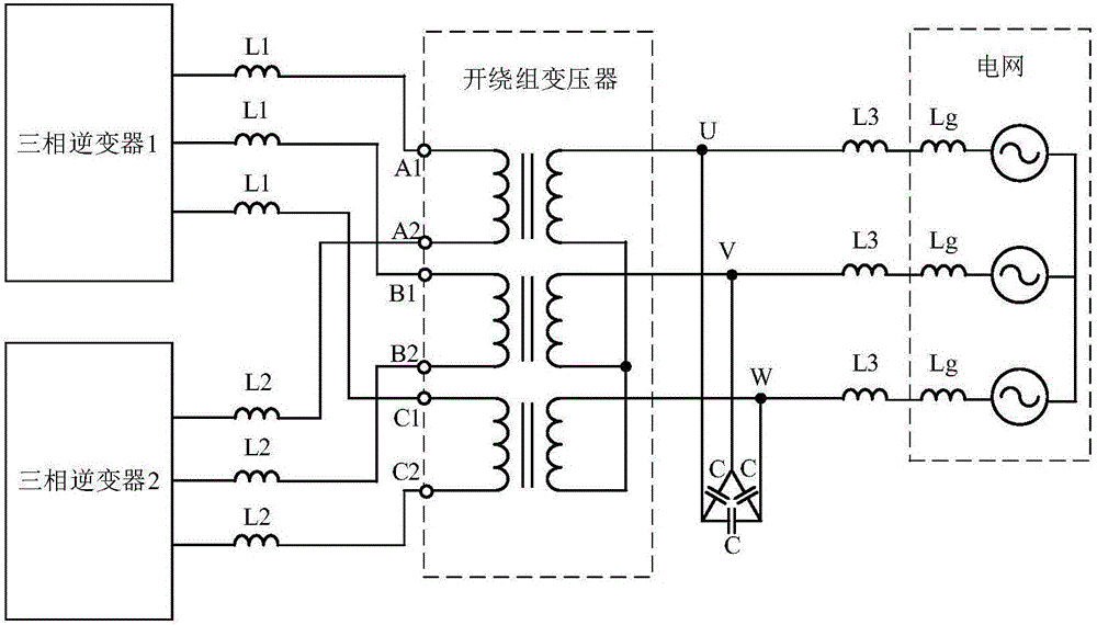
[0029] Based on the description of the first embodiment and the accompanying drawings, the second embodiment of the present invention discloses yet another output filter structure applied to an open-winding transformer-type dual inverter, see figure 2 The difference from the first embodiment is that the output filter includes two sets of primary three-phase filter reactance, namely three-phase filter reactance L1 and three-phase filter reactance L2; among them, three-phase filter reactance L1 has three filter reactances. One end is connected to the three-phase output bridge arm of the three-phase inverter 1, and the other end is connected to the primary three-phase terminals A1, B1, and C1 of the three-phase winding of the open-winding transformer; three filters of the three-phase filter reactance L2 One end of the reactance is respectively connected to the three-phase output bridge arm of the three-phase inverter 2, and the other end is respectively connected to the three-phase...

Embodiment 3

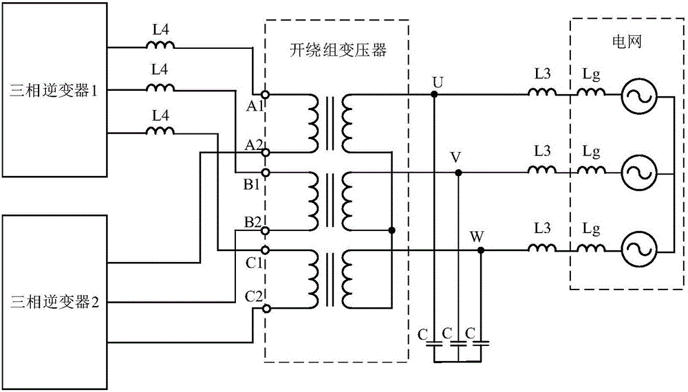
[0032] Based on the text description of the first embodiment and the accompanying drawings, the third embodiment of the present invention discloses yet another output filter structure applied to an open-winding transformer-type dual inverter, see image 3 The difference from the first embodiment is that the connection mode of the three-phase filter capacitor C is changed from a triangle to a star. For the description of the remaining parts of the third embodiment, refer to the first embodiment.


PUM


Abstract

The invention discloses an output filter applied to open winding transformer type dual inverters. The output filter comprises three-phase inverters 1 and 2 on the primary side of an open winding transformer, three-phase filtering electric reactors L3 and three-phase filtering capacitors C on the secondary side of the open winding transformer, wherein one ends of the three-phase filtering electric reactors L3 are connected with the secondary sides of the three-phase windings of the open winding transformer respectively while the other ends of the three-phase filtering electric reactors L3 are used as filter output to be connected with a power grid; the filter also comprises at least one group of primary side three-phase filtering electric rectors which consist of three primary side three-phase filtering electric rectors; and one ends of the three primary side three-phase filtering electric rectors are connected with three-phase output bridge arms of the three-phase inverter 1 or the three-phase inverter 2 respectively while the other ends of the three primary side three-phase filtering electric rectors are connected with the primary side three-phase terminals or separating side three-phase terminals of the three-phase windings of the open winding transformer respectively. According to the output filter, the characteristic that the output voltage harmonics of the two inverters are counteracted of the open winding transformer type dual inverter topology is fully utilized by combination with relatively high harmonic attenuation capability of the LCL filter, thereby greatly reducing the usage amount of filtering inductors and lowering the cost of the filter.

Description

Technical field [0001] The invention relates to the technical field of new energy grid-connected power generation, and more specifically, to an output filter applied to an open-winding transformer type double inverter. Background technique [0002] In order to increase the single-unit capacity of photovoltaic inverters or wind power inverters, the parallel inverter structure is widely used, and for boosting or isolation from the grid, the inverter needs to be connected to the grid through a transformer in parallel. For example, in the field of photovoltaic power generation, a typical solution is that two inverters are connected to the power grid through a dual-winding transformer or a dual-split transformer in parallel. [0003] In recent years, an open-winding transformer-type dual inverter topology has received extensive research and attention due to its excellent performance. This topology disassembles the original star or delta winding connection points on the low-voltage side...

Claims


Application Information

Patent Timeline
IPC IPC(8): H02M1/12H02J3/38
CPCH02M1/126H02J3/38
Inventor 王宝基张兴李飞曹仁贤
Owner HEFEI UNIV OF TECH
Learn More