Comprehensive overhaul platform of transformer
A technology for overhauling platforms and transformers, applied in switchgear, electrical components, etc.
- Summary
- Abstract
- Description
- Claims
- Application Information
AI Technical Summary
Problems solved by technology
Method used
Image
Examples
Embodiment 1
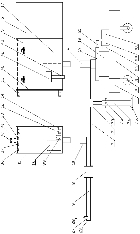
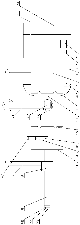
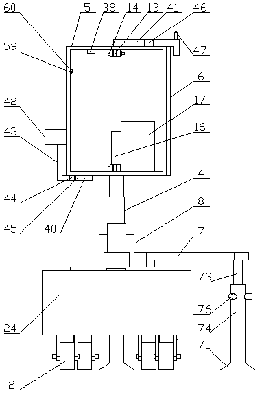
[0037] Embodiment 1: A transformer comprehensive maintenance platform, including a platform 1, a slewing mechanism arranged on the upper part of the platform 1, and a running mechanism 2 arranged at the bottom of the platform 1, and grooves are opened on the left and right sides of the platform 1 3. The upper part of the slewing mechanism is provided with a right elevating rod 4, the top of the right elevating rod 4 is provided with a right inspection box 5, and the right end of the right inspection box 5 is rotated to install a sealing door 6, and the upper part of the slewing mechanism is provided near the edge A half-frame support frame 7, the end of the half-frame support frame 7 is provided with a fixed sleeve 8, and a cantilever 9 is slidably arranged in the fixed sleeve 8, and a left elevating rod 10 is fixedly arranged on the upper surface of the right end of the cantilever 9, and the left elevating rod 10 is fixed on the upper surface of the right end of the cantilever ...
Embodiment 2
[0046] Embodiment 2: A transformer comprehensive maintenance platform, including a platform 1, a slewing mechanism arranged on the upper part of the platform 1, and a running mechanism 2 arranged at the bottom of the platform 1, and grooves are opened on the left and right sides of the platform 1 3. The upper part of the slewing mechanism is provided with a right elevating rod 4, the top of the right elevating rod 4 is provided with a right inspection box 5, and the right end of the right inspection box 5 is rotated to install a sealing door 6, and the upper part of the slewing mechanism is provided near the edge A half-frame support frame 7, the end of the half-frame support frame 7 is provided with a fixed sleeve 8, and a cantilever 9 is slidably arranged in the fixed sleeve 8, and a left elevating rod 10 is fixedly arranged on the upper surface of the right end of the cantilever 9, and the left elevating rod 10 is fixed on the upper surface of the right end of the cantilever ...
Embodiment 3
[0055] Embodiment 3: The difference between it and Embodiment 1 and Embodiment 2 is that: both the left elevating rod 10 and the right elevating rod 4 are hydraulic elevating rods.
[0056] The right end of the platform 1 is provided with a draw bar 25 , and a draw hole 26 is provided on the draw bar 25 .
[0057] An elastic layer 48 is provided on the right end surface of the left inspection box 11 and the left end surface of the right inspection box 5 .
[0058] The elastic layer 48 is made of wear-resistant rubber, and the wear-resistant rubber is composed of the following components in parts by weight: 70 parts of polyurethane rubber, 35 parts of acrylic rubber, 25 parts of nitrile rubber, 430 parts of styrene-butadiene rubber, brominated butyl 15 parts of ethylene rubber, 8 parts of polypropylene adiene siloxane, 15 parts of magnesium oxide, 20 parts of carbon black, 6 parts of urethane, 1.5 parts of polyethylene wax and 3 parts of carbon fiber. Due to the use of polyeth...
PUM
 Abstract
Description
Claims
Application Information
 - R&D
- Intellectual Property
- Life Sciences
- Materials
- Tech Scout
- Unparalleled Data Quality
- Higher Quality Content
- 60% Fewer Hallucinations
Browse by: Latest US Patents, China's latest patents, Technical Efficacy Thesaurus, Application Domain, Technology Topic, Popular Technical Reports.
© 2025 PatSnap. All rights reserved.Legal|Privacy policy|Modern Slavery Act Transparency Statement|Sitemap|About US| Contact US: help@patsnap.com


