
Iris positioning method and equipment

An iris positioning and iris technology, applied in the field of image processing, can solve the problems of long consumption time and low work efficiency of an iris recognition system, and achieve the effect of improving work efficiency

Active Publication Date: 2016-12-07
BEIJING INST OF RADIO METROLOGY & MEASUREMENT
View PDF5 Cites 11 Cited by
  • Summary
  • Abstract
  • Description
  • Claims
  • Application Information

AI Technical Summary

Problems solved by technology

[0012] In view of this, an embodiment of the present invention provides an iris locating method and device, which are used to solve the problem of low working efficiency of the iris locating system caused by the long time consumed in the iris locating process in the existing iris identifying system

Method used


Image

  • Iris positioning method and equipment
  • Iris positioning method and equipment
  • Iris positioning method and equipment

Examples


Embodiment 1

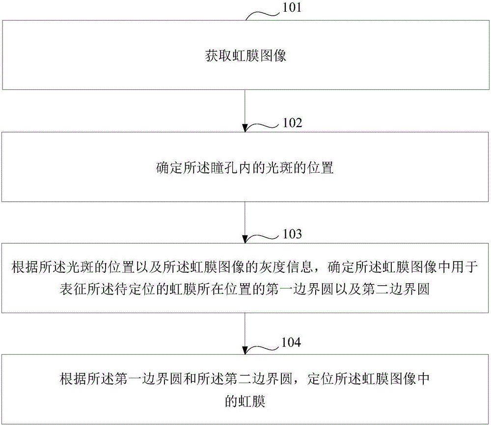
[0041] figure 1 It is a schematic flowchart of an iris positioning method provided by an embodiment of the present invention, and the method may be as follows.

[0042] Step 101: Obtain an iris image.

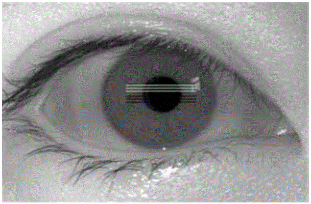
[0043] Wherein, the iris image includes iris and pupil to be positioned.

[0044] In step 101, the iris recognition system first performs an image acquisition operation to acquire an iris image, and then processes the acquired iris image to locate an iris in the iris image.

[0045] In practical applications, the iris image acquired by the iris recognition system may be an eye image including the iris to be located. For ease of understanding, the eye image is referred to as an iris image.

[0046] Step 102: Determine the position of the light spot in the pupil.

[0047] Wherein, the light spot is formed by an external light source entering the pupil.

[0048]In step 102, in the iris recognition system, in order to obtain better iris texture feature information, an external ...

Embodiment 2

[0171] Figure 8 A schematic structural diagram of an iris positioning device provided in an embodiment of the present invention, the iris positioning device includes: an acquisition unit 801, a first determination unit 802, a second determination unit 803, and a positioning unit 804, wherein:

[0172] An acquisition unit 801, configured to acquire an iris image, the iris image including the iris and pupil to be located;

[0173] The first determination unit 802 is configured to determine the position of the light spot in the pupil, the light spot is formed by an external light source entering the pupil;

[0174] The second determining unit 803 is configured to determine a first boundary circle and a second boundary in the iris image for representing the location of the iris to be located according to the position of the light spot and the grayscale information of the iris image a circle, the first bounding circle includes the center and radius of the first bounding circle, a...


PUM


Abstract

The invention discloses an iris positioning method and equipment. The method comprises steps that an iris identification system obtains an iris image which contains an iris and a pupil to be positioned; that the position of a light spot in the pupil is determined, wherein the light spot is formed by irradiating the pupil with an external light source; that according to the position of the light spot and the gray information of the iris image, a first boundary circle and a second boundary circle used for representing the iris to be positioned in the iris image are determined, wherein the first boundary circle comprises the center of circle and the radius of the first boundary circle, and the second boundary circle comprises the center of circle and the radius of the second boundary circle; and that according to the first boundary circle and the second boundary circle, the iris in the iris image can be positioned. Therefore, the iris identification system can rapidly position the position of the iris by a simple image processing technology and a curve fitting algorithm according to the obtained gray information of the iris image, so that the working efficiency of the iris identification system is improved.

Description

technical field [0001] The invention relates to the technical field of image processing, in particular to an iris positioning method and device. Background technique [0002] Iris recognition technology is a kind of biometric identification technology, which has the advantages of uniqueness, stability, security and non-contact, etc. It is a research hotspot and development trend in the field of biometric identification. [0003] The iris recognition system mainly includes steps such as image acquisition, image preprocessing, iris feature extraction and feature matching. First, the iris recognition system performs image acquisition to obtain an eye image containing an iris image. [0004] Secondly, the iris recognition system performs image preprocessing on the eye image to determine the position of the iris in the eye image. Specifically, the iris is a part of the eye structure, located between the pupil and the sclera, and the position of the iris in the eye image is dete...

Claims


Application Information

Patent Timeline
IPC IPC(8): G06K9/00
CPCG06V40/193
Inventor 杨倩倩郭慧杰
Owner BEIJING INST OF RADIO METROLOGY & MEASUREMENT
Learn More