
A hydraulic clamping device for high-frequency fatigue test of thin-walled flat specimens

A fatigue test and hydraulic clamping technology, applied in the field of high-frequency fatigue test, can solve problems such as stress relaxation, and achieve the effect of solving stress relaxation, good controllability, ease of processing, and good reliability

Active Publication Date: 2018-10-23
NORTHWESTERN POLYTECHNICAL UNIV
View PDF11 Cites 0 Cited by
  • Summary
  • Abstract
  • Description
  • Claims
  • Application Information

AI Technical Summary

Problems solved by technology

The clamping device adopts an external hydraulic power source and is equipped with a cooling system, which can ensure good reliability and clamping performance under the experimental conditions of up to 1100°C, large load, and high frequency, and overcomes the existing technology. Stress relaxation problem of fixture in high temperature environment

Method used


Image

  • A hydraulic clamping device for high-frequency fatigue test of thin-walled flat specimens
  • A hydraulic clamping device for high-frequency fatigue test of thin-walled flat specimens
  • A hydraulic clamping device for high-frequency fatigue test of thin-walled flat specimens

Examples


Embodiment Construction

[0031] This embodiment is a hydraulic clamping device used for high frequency fatigue test of thin-walled flat test piece.

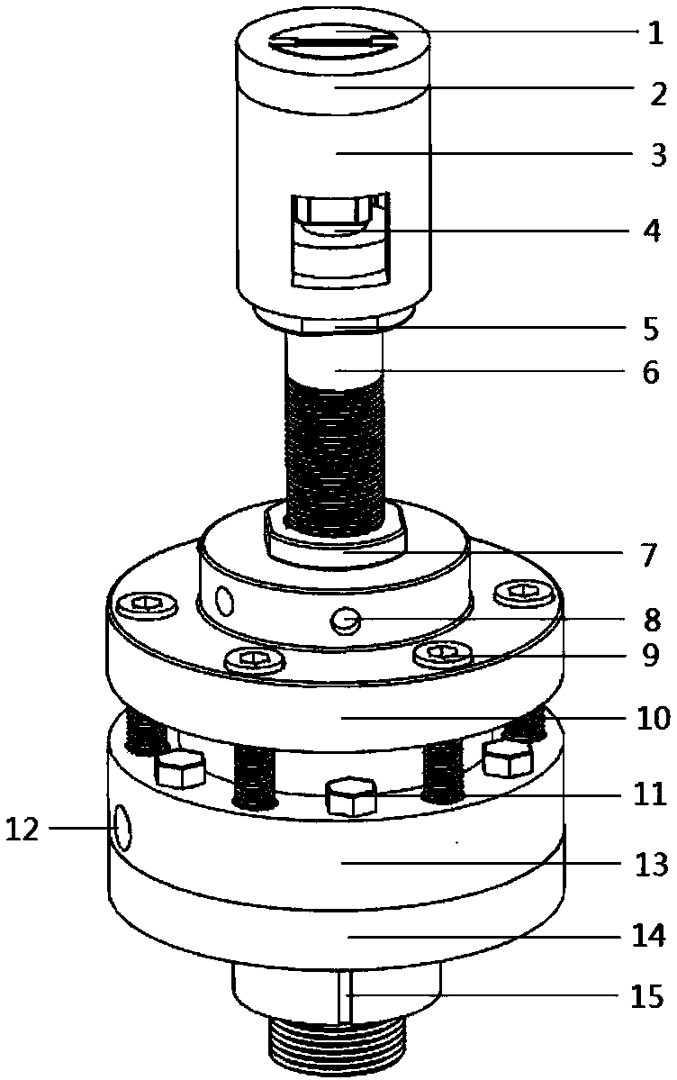
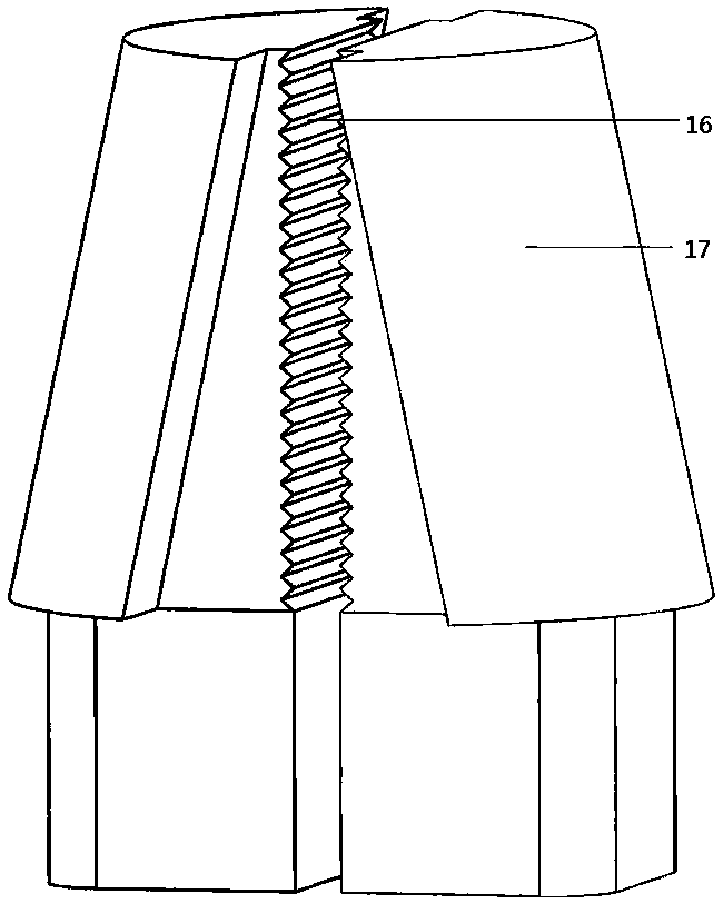
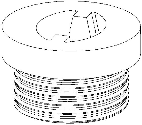
[0032] Refer to Figure 1 ~ Figure 12 This embodiment is used for the hydraulic clamping device for the high-frequency fatigue test of thin-walled flat specimens. It consists of a slider 1, a collet cover 2, a sleeve 3, a piston 4, an upper nut 5, a strut 6, a nut 7, and a cooling nozzle. 8. Bolt 9, water cooling plate 10, hexagonal bolt 11, hydraulic oil inlet 12, hydraulic cylinder 13, hydraulic chassis 14, lower nut 15, serrated teeth 16, slider arc 17, arc chute 18, rectangular hole 19 , Countersunk screw hole 20, spring 21, spring interface 22, hydraulic oil outlet 23; according to the strength requirements of the fatigue test, K403 is selected as the fixture material. Among them, the hydraulic cylinder 13 is disc-shaped, with multiple screw holes evenly distributed around the edge. The bottom of the middle cavity is processed with a hydraulic oil out...


PUM


Abstract

The invention discloses a high-frequency fatigue test hydraulic clamping device for a thin-wall plate test piece. The high-frequency fatigue test hydraulic clamping device is composed of an electro-hydraulic press, a hydraulic base, an external water circulation cooling disc, a hollow stay bar for hydraulic power transmission, a sleeve for connecting the stay bar and a clamping head cover, the clamping head cover with an internal cambered surface sliding groove and a thread, and a cambered surface wedge-shaped sliding block used for clamping the plate test piece. According to the clamping device, hydraulic pressure is adopted as clamping power, the problem of stress relaxation caused by high-temperature metal creep or expansion and high-frequency vibration is solved, and the peak value of an allowable load is increased by two times or above compared with that of a bolt-on clamp; a water circulation cooling system is arranged, and through the design of water cooling and the high-temperature alloy sliding block, it can be guaranteed that the clamping device has good reliability and clamping stability under the experiment conditions of a high temperature (1100 DEG C), a large load and high frequency; the cambered surface wedge-shaped sliding block slides in the internal cambered surface sliding groove of the clamping head cover, the clamping width can be adjusted, and the clamping device is wide in application range and has good controllability and workability.

Description

Technical field [0001] The invention relates to a high-frequency fatigue test technology under high temperature and high stress, in particular to a hydraulic clamping device for high-frequency fatigue test of thin-walled flat test pieces. technical background [0002] With the development of science and technology, the performance of materials at high temperatures has been continuously improved, and the heat resistance of metals has increased at a rate of about 8°C per year. When conducting the necessary high-cycle fatigue performance research, the test technology of rod-shaped specimens with threaded connections has become mature. However, in the aviation field, turbine engine blades mainly exist in the form of plates and vibrate at high frequencies in high temperature environments. The rod-shaped specimens cannot truly simulate the actual operating conditions of the engine blades. Because the superalloy material is brittle at low temperature, it is difficult to process the ro...

Claims


Application Information

Patent Timeline
Patent Type & Authority Patents(China)
IPC IPC(8): G01N3/04
CPCG01N3/04G01N2203/0411
Inventor 温志勋吴云伍刘晨宇岳珠峰
Owner NORTHWESTERN POLYTECHNICAL UNIV
Learn More