


Quick Research
Generate reliable direction feasibility study reports for your R&D in just a few steps.

Technical Q&A
Discover and master advanced knowledge NOW. Basics, ideas, possibilities, all at once.

Find Solutions
As an expert in R&D theories, this can generate solutions to your technical problems instantly.

Evaluate Feasibility
Analyze your overall solution with one click, know your potential R&D risks in advance.

Monitor Landscape
Get weekly tech updates, stay abreast of the latest tech innovations and key insights.
Cooling device and working method thereof
A cooling device and workbench technology, which is applied to household refrigeration devices, lighting and heating equipment, household appliances, etc., can solve problems such as uneven temperature, and achieve the effects of improving production quality, applicability, and quality
- Summary
- Abstract
- Description
- Claims
- Application Information
AI Technical Summary
Problems solved by technology
Method used
Image

Examples
Embodiment 1
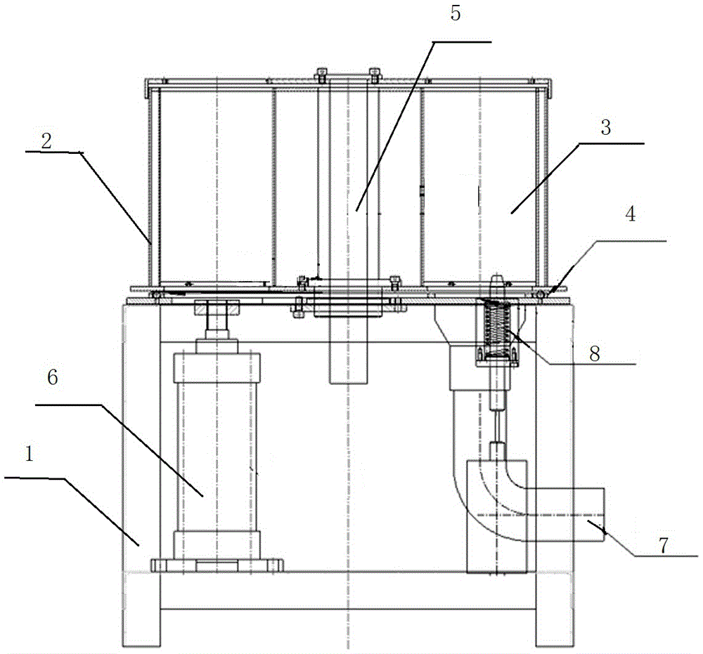
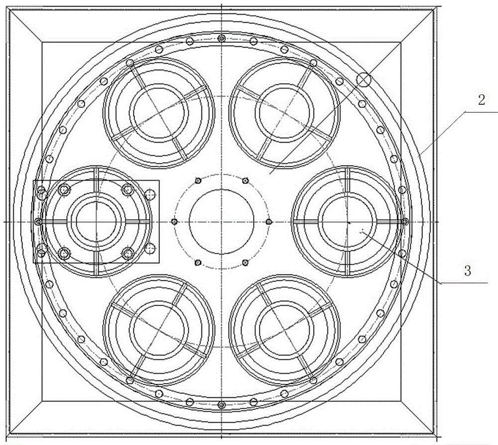
[0035] Such as figure 1 with figure 2 A cooling device shown includes: a control box 1 and a barrel 2 and a control device, wherein the barrel 2 is provided with a storage barrel 3, and the barrel 2 is arranged above the control box 1. And, a rotating mechanism 4 is provided between the control box 1 and the barrel 2, and the control box 1 and the barrel 2 are connected by a central shaft 5, and the control box 1 is provided with a pusher The power system 6 and the air intake device 7, the pushing power system 6 and the air intake device 7 are all matched with the storage tank 3, and the rotating mechanism 4, the pushing power system 6 and the air intake device 7 are all compatible with Control device connection.
[0036] In the present embodiment, the air intake device 7 is provided with an air inlet duct and an air volume regulator. The air volume regulator is arranged at the tuyere of the air inlet duct, and the control box 1 and the barrel 2 are arranged between There is a...
Embodiment 2
[0043] The structure of the cooling device in the working method of the cooling device described in this embodiment is the same as that in the first embodiment.
[0044] Such as figure 1 with figure 2 A cooling device shown includes: a control box 1 and a barrel 2 and a control device, wherein the barrel 2 is provided with a storage barrel 3, and the barrel 2 is arranged above the control box 1. And, a rotating mechanism 4 is provided between the control box 1 and the barrel 2, and the control box 1 and the barrel 2 are connected by a central shaft 5, and the control box 1 is provided with a pusher The power system 6 and the air intake device 7, the pushing power system 6 and the air intake device 7 are all matched with the storage tank 3, and the rotating mechanism 4, the pushing power system 6 and the air intake device 7 are all compatible with Control device connection.
[0045] In the present embodiment, the air intake device 7 is provided with an air inlet duct and an air v...
PUM
 Abstract
Description
Claims
Application Information
 - R&D Engineer
- R&D Manager
- IP Professional
- Industry Leading Data Capabilities
- Powerful AI technology
- Patent DNA Extraction
Browse by: Latest US Patents, China's latest patents, Technical Efficacy Thesaurus, Application Domain, Technology Topic, Popular Technical Reports.
© 2024 PatSnap. All rights reserved.Legal|Privacy policy|Modern Slavery Act Transparency Statement|Sitemap|About US| Contact US: help@patsnap.com