
Gas-liquid separation conveying pump

A technology for gas-liquid separation and delivery pumps, which is applied in the direction of pumps, pump components, non-variable pumps, etc., and can solve problems such as complex structures, high liquid delivery costs, and increased delivery costs

Active Publication Date: 2016-12-07
XIHUA UNIV
View PDF6 Cites 2 Cited by
  • Summary
  • Abstract
  • Description
  • Claims
  • Application Information

AI Technical Summary

Problems solved by technology

When the gas content reaches or exceeds 10%, the liquid cannot be transported through the hydraulic pump. Therefore, it is necessary to add a separate gas-liquid separation auxiliary equipment to separate the gas-liquid in the liquid medium before transporting. Caused an increase in transportation costs, and the structure is complex and the application convenience is low
[0003] In the above existing technologies, the defects such as high cost of liquid transportation, complicated structure and low application convenience are technical problems that need to be solved by those skilled in the art

Method used


Image

  • Gas-liquid separation conveying pump
  • Gas-liquid separation conveying pump
  • Gas-liquid separation conveying pump

Examples


Embodiment Construction

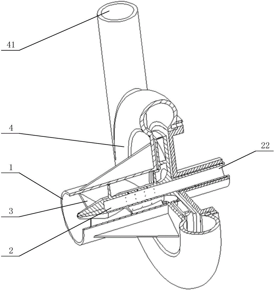
[0018] The core of the present invention is to provide a gas-liquid separation transport pump, through the application of the present invention, the convenience of liquid transport will be significantly improved, while the cost and structural complexity will be reduced.

[0019] The following will clearly and completely describe the technical solutions in the embodiments of the present invention with reference to the accompanying drawings in the embodiments of the present invention. Obviously, the described embodiments are only some, not all, embodiments of the present invention. Based on the embodiments of the present invention, all other embodiments obtained by persons of ordinary skill in the art without making creative efforts belong to the protection scope of the present invention.

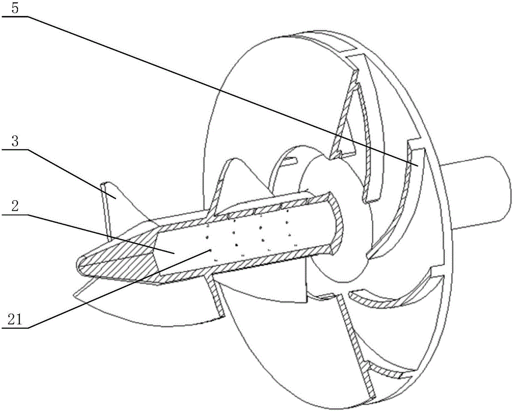
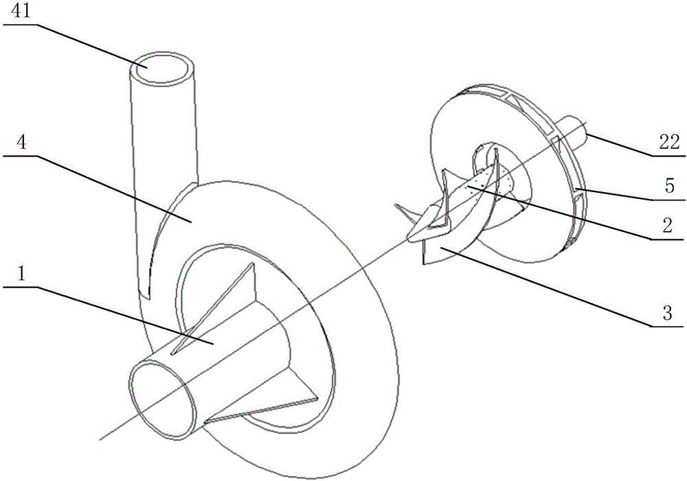
[0020] Please refer to Figure 1 to Figure 3 , figure 1 It is the first schematic diagram of the structure of the present invention; figure 2 It is the second schematic diagram of the stru...


PUM


Abstract

The invention relates to the technical field of fluid conveying, in particular to a gas-liquid separation conveying pump. The gas-liquid separation conveying pump comprises a tubular shell, an exhaust pipe capable of rotating, a helical blade, a volute and a straight blade. The volute is connected to the tail end of the tubular shell and communicates with the tubular shell. The head end of the tubular shell is provided with an input opening. The exhaust pipe is arranged between the tubular shell and the volute in the longitudinal direction. The side wall of the exhaust pipe is provided with an air inlet. The tail end of the exhaust pipe is provided with an exhaust outlet communicating with the air inlet. The exhaust outlet is formed in the outer side of the volute. The helical blade is installed on the exhaust pipe and located in the tubular shell. The straight blade is installed on the exhaust pipe and located in the tubular shell. The radial direction of the volute is provided with a liquid discharge outlet used for discharging liquid. Through application of the gas-liquid separation conveying pump, gas-liquid separation is completed during conveying, thus application convenience is improved significantly, and the cost and structure complexity are reduced.

Description

technical field [0001] The invention relates to the technical field of fluid delivery, in particular to a gas-liquid separation delivery pump. Background technique [0002] At present, in various industries, it is often necessary to transport liquid media containing more gas, and the gas content in liquid media greatly affects the transmission efficiency. When the gas content reaches or exceeds 10%, the liquid cannot be transported through the hydraulic pump. Therefore, it is necessary to add a separate gas-liquid separation auxiliary equipment to separate the gas-liquid in the liquid medium before transporting. Caused the increase of conveying cost, and the structure is complicated, and the convenience of application is low. [0003] In the above prior art, the defects such as high cost of liquid transportation, complicated structural arrangement, and low convenience of application are technical problems that need to be solved by those skilled in the art. Contents of the...

Claims


Application Information

Patent Timeline
IPC IPC(8): F04D7/02F04D29/00F04D29/24F04D29/42
CPCF04D7/02F04D29/007F04D29/242F04D29/245F04D29/426
Inventor 叶道星赖喜德张翔史广泰秦浩
Owner XIHUA UNIV
Learn More