
Air conditioning system for automobile based on vortex pipe

An air conditioning system, vortex tube technology, applied in air handling equipment, vehicle components, heating/cooling equipment, etc., can solve problems such as unstable gas flow, increased vehicle energy consumption, aggravated environmental problems, etc., to achieve stable gas source, The effect of reducing vehicle energy consumption and easy lightweighting

Inactive Publication Date: 2016-12-07
ZHEJIANG UNIV
View PDF6 Cites 15 Cited by
  • Summary
  • Abstract
  • Description
  • Claims
  • Application Information

AI Technical Summary

Problems solved by technology

At present, the main refrigerant used in the field of automotive air conditioning is R134a. Although this refrigerant has no destructive effect on ozone (ODP=0), it still causes a certain greenhouse effect (GWP=1300). Considering the current number of cars In billions, the climate warming effect caused by the refrigerant discharged into the atmosphere during the production and use of automobile air conditioners is very obvious. At present, countries have begun to limit the GWP value of refrigerants in automobile air conditioners
Second, the current automobiles use a large amount of fossil energy as the main power source. For non-independent automobile air-conditioning systems, the compressor of the air-conditioning system is driven by the automobile engine, so the use of automobile air-conditioning will directly cause the automobile Increased energy consumption, thereby exacerbating environmental problems
The scheme reported in this patent document can realize the utilization of solar energy very well and save the energy consumption of the car, but this patent document uses the energy generated during the braking process of the car to compress the gas. The energy in this process is less, and the gas flow obtained by compression Unstable etc.
At the same time, the system is relatively complex, requiring the combination of pumps, fans, heat exchangers, etc.

Method used


Image

  • Air conditioning system for automobile based on vortex pipe
  • Air conditioning system for automobile based on vortex pipe
  • Air conditioning system for automobile based on vortex pipe

Examples


Embodiment 1

[0059] Embodiment 1 Directly adjust the air temperature in the compartment under the summer working mode

[0060] In summer, due to the sun's rays, the temperature in the compartment rises rapidly. At the same time, because the environment in the compartment has a certain degree of airtightness, the temperature in the compartment can be as high as 50-60°C. The temperature is lowered. This embodiment will mainly illustrate the process of cooling the air inside the compartment under the present invention under this working condition.

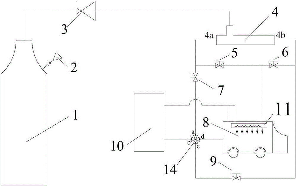
[0061] as attached figure 1 As shown, the working fluid flowing out of the high-pressure tank 1 becomes a low-pressure gas after passing through the pressure-reducing valve 4, and flows into the vortex tube 4 at this pressure for energy separation. The working fluid is separated into two streams after passing through the vortex tube 4, one is a high-temperature fluid, and the other is a low-temperature fluid. At this time, the stop valve 5 and ...

Embodiment 2

[0067] Example 2 Adjust the air temperature in the compartment through the heat exchanger in the summer working mode

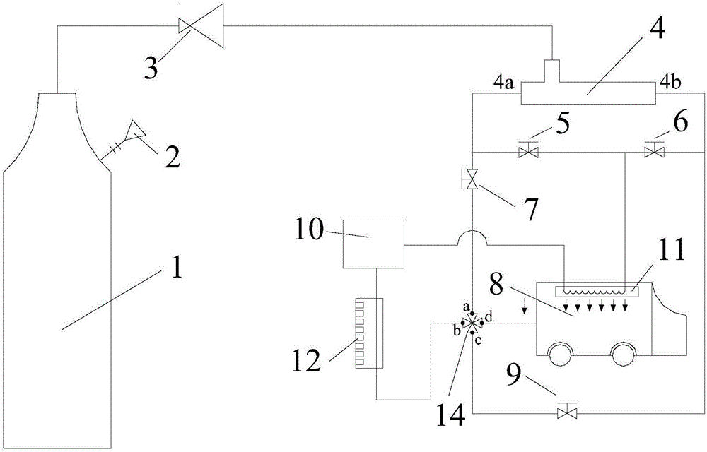
[0068] By adjusting the position of the orifice plate, the temperature of the fluid at the outlet 4a of the cold end of the vortex tube 4 is much lower than normal temperature, then the cold fluid at this time cannot be directly discharged into the interior of the compartment, but its cooling capacity is introduced through a heat exchange structure to the interior of the carriage. This embodiment will be used to illustrate the working process of a vortex tube-based automobile air-conditioning system proposed by the present invention applied in this working mode.

[0069] as attached figure 2 As shown, the working fluid flowing out of the high-pressure tank 1 becomes a low-pressure gas after passing through the pressure-reducing valve 3, and flows into the vortex tube 4 at this pressure for energy separation. The working fluid is separated into two streams a...

Embodiment 3

[0073] Embodiment 3 Directly adjust the air temperature in the compartment under the winter working mode

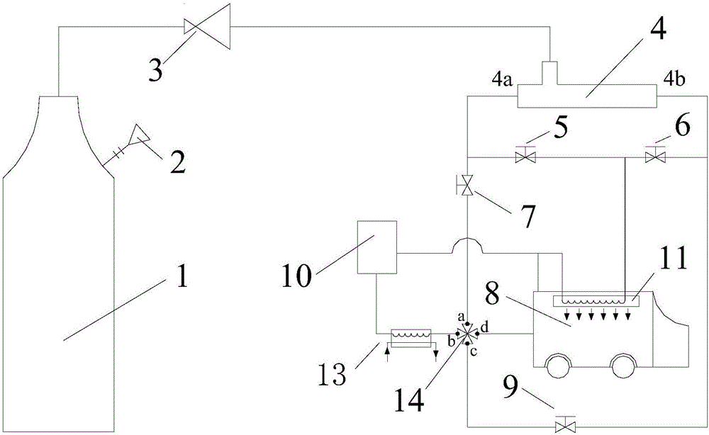
[0074] In winter, the radiation effect of the sun is obviously weakened, and the temperature of the surrounding environment is also relatively low. At this time, the application of the automotive air conditioning system is mainly to increase the temperature in the cabin to make the environment matter. This embodiment will mainly illustrate the process of raising the temperature of the air inside the compartment when the present invention is applied in this working condition.

[0075] as attached image 3 As shown, the working fluid flowing out of the high-pressure tank 1 becomes a low-pressure gas after passing through the pressure-reducing valve 3, and flows into the vortex tube 4 at this pressure for energy separation. The working fluid is separated into two streams after passing through the vortex tube, one is high temperature fluid and the other is low temperature fl...


PUM


Abstract

The invention discloses an air conditioning system for an automobile based on a vortex pipe. The air conditioning system comprises an air supply unit, a heat exchanger, and the vortex pipe, wherein the heat exchanger is arranged in the automobile; an inlet of the vortex pipe is connected with the air supply unit; and one outlet of a hot end outlet and a cold end outlet of the vortex pipe is connected with an inlet of a heat exchanging medium pipeline of the heat exchanger, and the other outlet of the hot end outlet and the cold end outlet of the vortex pipe communicates with the surrounding environment. In summer, cold fluid is cooled by the heat exchanger in the automobile or directly introduced in a compartment for cooling, and in winter, hot fluid can also be heated by the heat exchanger in the automobile or directly introduced in the compartment for heating. The air conditioning system disclosed by the invention has the outstanding advantages of being simple in device, high in reliability, small in occupied space, high in energy utilization efficiency and the like, and has good application prospects in the field of air conditioning in automobiles.

Description

technical field [0001] The invention relates to the fields of vortex tube energy separation and automobile air quality regulation, in particular to an air conditioning system realized in a car compartment by using a vortex tube. Background technique [0002] In today's society, cars have become one of the indispensable tools for people to travel, and they are playing an increasingly important role in daily life. At present, my country's automobile ownership and annual output are among the top in the world. According to the statistics of China Association of Automobile Manufacturers, in the next few years, my country's automobile production will still maintain a relatively rapid development speed. At the same time, the development of technology also makes people pursue a better living and working environment. As an important tool in urban life, the improvement of the air quality in the car compartment has gradually become a hot spot for people to pay attention to. Therefore, ...

Claims


Application Information

Patent Timeline
IPC IPC(8): B60H1/00B60H1/32F25B9/04
CPCF25B9/04B60H1/00492B60H1/3204
Inventor 韩晓红王学会华超杨璋璋方一波王征乔晓刚陈光明
Owner ZHEJIANG UNIV
Learn More