Toothed belt
A toothed belt and tooth technology, applied in the direction of transmission belts, belts/chains/gears, mechanical equipment, etc., can solve problems such as unseen belt speed changes, improve dimensional stability, improve bendability, and ensure dimensional stability sexual effect
- Summary
- Abstract
- Description
- Claims
- Application Information
AI Technical Summary
Problems solved by technology
Method used
Image


Examples
no. 1 approach
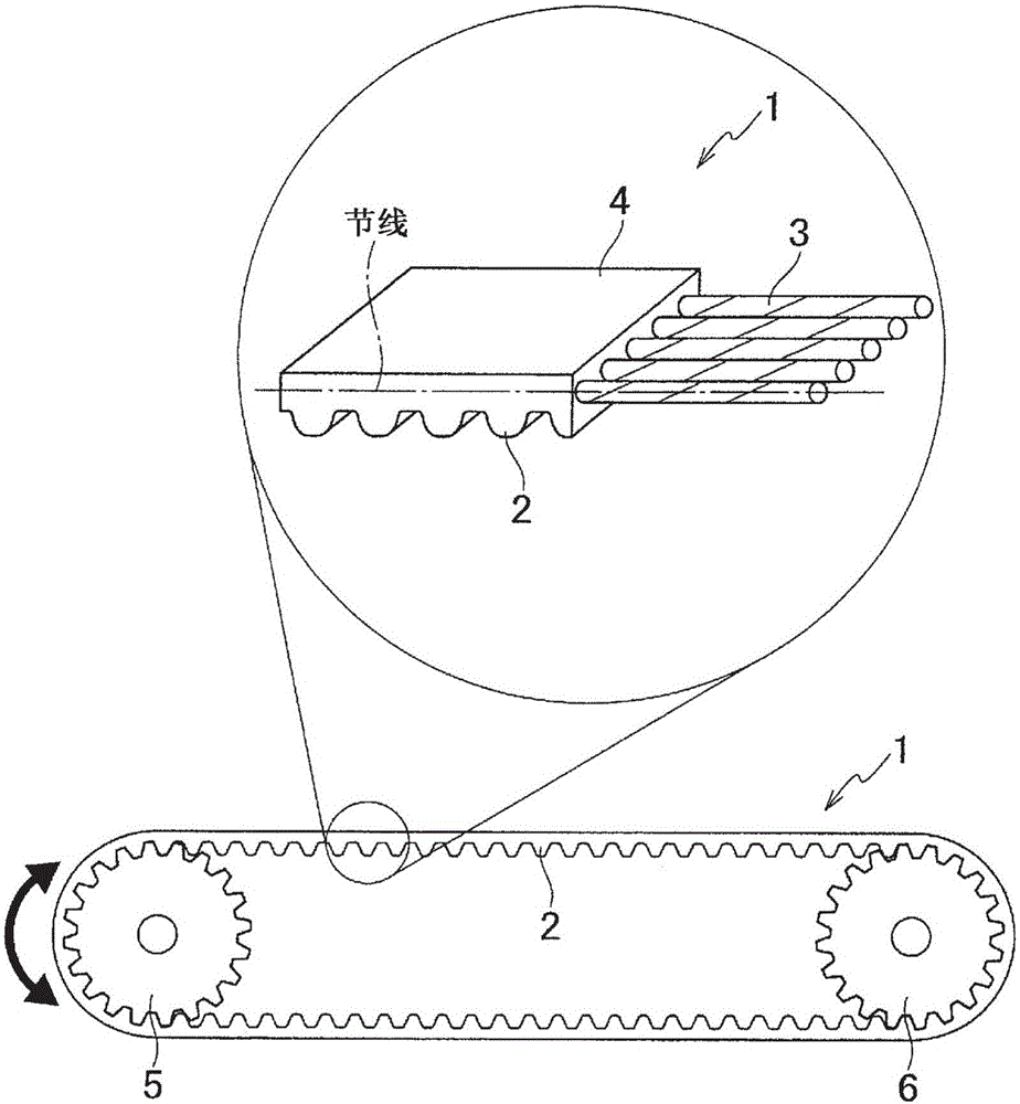
[0060] Such as figure 1 As shown, the toothed belt 1 of the first embodiment is used while being wound between the driving pulley 5 and the driven pulley 6 . Thereby, synchronous transmission can be performed between the driving pulley 5 and the driven pulley 6 .
[0061] The toothed belt 1 is composed of a plurality of teeth 2 along the belt length direction, a core wire 3 as a reinforcing core on the pitch line of the toothed belt 1 , and a back portion 4 in which the core wire 3 is embedded. and, figure 2 The distance between the tooth parts 2 shown in (B), that is, the tooth pitch is 0.45 to 0.60 mm. The shape of the tooth portion 2 is a scalloped shape, but it is not limited thereto, and may be arbitrarily selected from a cross-sectional trapezoidal shape, a cross-sectional triangular shape, and the like.
[0062] The tooth portion 2 and the back portion 4 of the toothed belt 1 are made of a polyurethane resin composition. The polyurethane resin composition is obtain...
no. 2 approach
[0072] Next, a second embodiment of the present invention will be described. It should be noted that descriptions of the same elements as those in the first embodiment will be appropriately omitted. That is, for elements not specifically described below, the same explanations as those corresponding to elements in the above-mentioned first embodiment are applied.
[0073] The toothed belt 1 according to the second embodiment includes a plurality of tooth portions 2 along the belt length direction, a core wire 3 as a reinforcing core on the pitch line of the toothed belt 1 , and a back portion 4 in which the core wire 3 is buried. . and, figure 2 The distance between the tooth parts 2 shown in (B), that is, the tooth pitch is 0.45 to 0.71 mm.
[0074] The core wire 3 is a stranded wire formed by twisting polyarylate fiber filaments, for example, a total of 110 dtex monofilaments (original yarn) bundled and paralleled with 20 polyarylate fiber filaments (filament fineness) wi...
Embodiment
[0076] Next, using the toothed belt having the structure of each embodiment of the present invention as an example and the toothed belt not having the structure of each embodiment as a comparative example, 1. Speed variation test, 2. Endurance movement Test, 3. with dimensional stability test, 4. with bending test.
[0077] (1. Speed change rate test)
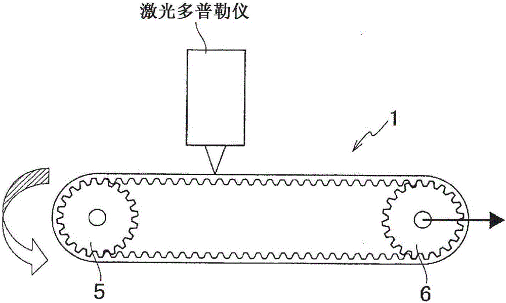
[0078] In the speed change rate test, the laser Doppler was used to measure the image 3 The two-axis layout shown makes the speed of the toothed belt 1 uneven when moving, and the belt speed variation rate (%) at the primary meshing frequency was obtained by frequency analysis.
[0079] Specifically, as image 3As shown, a toothed belt 1 is stretched between the driving pulley 5 and the driven pulley 6 (the driving pulley 5 and the driven pulley 6 are toothed pulleys with the same number of teeth, pitches, and pitch circle diameters). The tension of the driven pulley 6 is moved, and a predetermined axial load (5N, 10N, ...
PUM
| Property | Measurement | Unit |
|---|---|---|
| diameter | aaaaa | aaaaa |
Abstract
Description
Claims
Application Information
 - R&D
- Intellectual Property
- Life Sciences
- Materials
- Tech Scout
- Unparalleled Data Quality
- Higher Quality Content
- 60% Fewer Hallucinations
Browse by: Latest US Patents, China's latest patents, Technical Efficacy Thesaurus, Application Domain, Technology Topic, Popular Technical Reports.
© 2025 PatSnap. All rights reserved.Legal|Privacy policy|Modern Slavery Act Transparency Statement|Sitemap|About US| Contact US: help@patsnap.com