Sputtering target comprising al-te-cu-zr alloy and method of making the same
An al-te-cu-zr and manufacturing method technology, which is applied to the Al-Te-Cu-Zr alloy sputtering target and its manufacturing field, can solve the problems of uneven film formation speed, large difference in sputtering rate, etc. Suppression of particles, uniform film formation speed, and reduction of oxygen content
- Summary
- Abstract
- Description
- Claims
- Application Information
AI Technical Summary
Problems solved by technology
Method used
Image
Examples
Embodiment 1
[0061] The Cu raw material with a purity of 4N and the Te raw material with a purity of 5N were weighed to obtain a composition of Cu:Te=30:70 (atomic %). As raw materials, Cu wires and Te particles of a size that can be put in a synthetic ampoule are selected. Next, in order to prevent oxidation during smelting and contamination from the outside, the raw materials were put into a high-purity quartz ampoule and vacuum sealed. When selecting ampoules, use ampoules with an inner diameter of 80mm and a length of 200mm to reduce the temperature distribution and make the melt easy to mix uniformly. Then, for alloying, melting is performed. Keep it at 1000°C for 4 hours to fully react and melt Cu and Te. At this time, in order to make the melt uniform, shake at a cycle of 30 Hz. After the smelting, it was slowly cooled to room temperature in the furnace to produce an ingot. Through the above method, a high-purity CuTe ingot with a purity of 4N was obtained.
[0062] Next, the ingo...
Embodiment 2
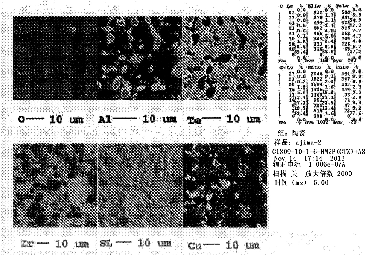
[0067] Except that the sintering temperature (maximum) of the mixed powder of CuTe powder and Zr powder was changed from 400°C to 500°C (liquid phase reaction), a sintered body was produced under the same conditions as in Example 1. Thus, an Al-Te-Cu-Zr alloy sintered body having a purity of 3N or higher, an oxygen concentration of 2900 ppm by weight, a relative density of 93%, and an average particle size of 9 μm was obtained. In addition, it was confirmed that the sintered body structure was composed of Al phase, CuAl phase, TeZr phase, and Zr phase. Next, a sputtering target was produced by machining the sintered body, and sputtering was performed using the target under the same conditions as in Example 1. As a result, there were 18 particles (0.2 μm or more) with very few particles.
Embodiment 3
[0069] Furthermore, the CuTe powder with a particle size of 90 μm or less produced in Example 1 was pulverized by a jet mill. The maximum particle size after pulverization was 5 μm, and the oxygen content was 680 ppm by weight. Next, hydrogen reduction was performed under the same conditions as in Example 1 to obtain a low-oxygen powder having an oxygen concentration of 80 ppm by weight. Weigh and mix CuTe powder with a maximum particle size of 5 μm and an oxygen concentration of 80 wt ppm, Al powder with a maximum particle size of 10 μm and an oxygen concentration of 5,100 wt ppm, and a maximum particle size of 10 μm and an oxygen concentration of 8000 wt ppm. Zr powder to obtain the same composition as in Example 1. This raw material powder was filled in a graphite mold with a diameter of 480 mm and hot-pressed to produce a sintered body. The sintering conditions were set in the same manner as in Example 1: sintering temperature 325°C, pressure 300kgf / cm 2 、Holding time is ...
PUM
| Property | Measurement | Unit |
|---|---|---|
| particle size | aaaaa | aaaaa |
| particle size | aaaaa | aaaaa |
| particle diameter | aaaaa | aaaaa |
Abstract
Description
Claims
Application Information
 - R&D
- Intellectual Property
- Life Sciences
- Materials
- Tech Scout
- Unparalleled Data Quality
- Higher Quality Content
- 60% Fewer Hallucinations
Browse by: Latest US Patents, China's latest patents, Technical Efficacy Thesaurus, Application Domain, Technology Topic, Popular Technical Reports.
© 2025 PatSnap. All rights reserved.Legal|Privacy policy|Modern Slavery Act Transparency Statement|Sitemap|About US| Contact US: help@patsnap.com


