Operational Amplifier

A technology of operational amplifiers and amplifying circuits, applied in amplifiers, differential amplifiers, DC-coupled DC amplifiers, etc., can solve problems such as phase reduction, and achieve the effects of no power consumption, improved stability, and simple circuits

Active Publication Date: 2019-04-09
SHANGHAI HUAHONG GRACE SEMICON MFG CORP
View PDF6 Cites 0 Cited by
  • Summary
  • Abstract
  • Description
  • Claims
  • Application Information

AI Technical Summary

Problems solved by technology

[0007] It can be seen that the structure of the second-stage amplifier introduces two poles, and the capacitor Cm forms Miller compensation to widen the distance between the two poles, but the capacitor Cm also forms a gap between the first-stage amplified signal and the second-stage amplified signal. Feed-forward path, the feed-forward path will bring a right-half-plane zero point, the right-half-plane zero point will not only increase the gain but also reduce the phase, thus increasing the instability of the circuit

Method used


Image

  • Operational Amplifier
  • Operational Amplifier
  • Operational Amplifier

Examples


Embodiment Construction

[0025] The technical solutions of the present invention will be clearly and completely described below in conjunction with the accompanying drawings. Apparently, the described embodiments are part of the embodiments of the present invention, not all of them. Based on the embodiments of the present invention, all other embodiments obtained by persons of ordinary skill in the art without making creative efforts belong to the protection scope of the present invention.

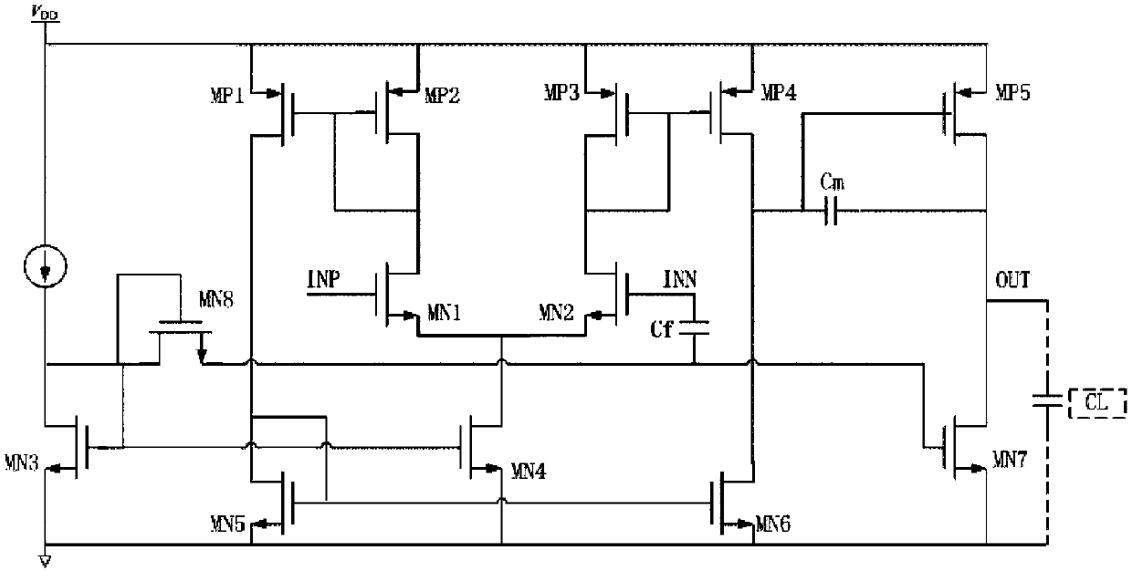
[0026] Such as figure 2 Shown is the preferred embodiment of the circuit diagram of the operational amplifier of the present invention, and the operational amplifier of the present invention comprises:

[0027] The first-stage amplifying circuit is a single-end output differential amplifier circuit; the input pair of the single-end output differential amplifier circuit is composed of the first MOS transistor MN1 and the second MOS transistor MN2; the gate of the first MOS transistor MN1 is The non-inverting inpu...


PUM


Abstract

The invention discloses an operational amplifier, which comprises a first-stage amplifier circuit and a second-stage amplifier circuit, wherein the first-stage amplifier circuit is a single-ended output differential amplifier circuit; a grid of a first MOS (Metal Oxide Semiconductor) transistor and a grid of a second MOS transistor are respectively taken as a non-inverting input terminal and an inverting input terminal of the single-ended output differential amplifier circuit; a drain of an eleventh PMOS (P-channel Metal Oxide Semiconductor) tube is taken as an inverting output terminal and outputs a first-stage amplifying signal; an input end of the second-stage amplifier circuit is connected to the first-stage amplifying signal; and a seventh MOS transistor is connected to an output end of the second-stage amplifier circuit and provides current source load for the second-stage amplifier circuit. A second capacitor and the seventh MOS transistor form a feedforward path between the inverting input terminal of the single-ended output differential amplifier circuit and the output end of the second-stage amplifier circuit; the transconductance of the seventh transistor is arranged to be greater than the transconductance of the first-stage amplifier circuit, so that the operational amplifier forms left half plane zero to offset a pole in order to realize an effect of improving the stability of the circuit.

Description

technical field [0001] The invention relates to a semiconductor integrated circuit, in particular to an operational amplifier capable of improving stability. Background technique [0002] Operational amplifiers (Operational Amplifiers) are widely used in integrated circuits, and stability is one of the important indicators of operational amplifiers. [0003] Such as figure 1 As shown, it is the circuit diagram of the existing operational amplifier: the input tube of the differential amplifier circuit is composed of NMOS tube MN1 and NMOS tube MN2, the drains of PMOS tube MP1 and NMOS tube MN1 are connected to the active load of NMOS tube MN1, and the PMOS tube MP2 and The drain of the NMOS transistor MN2 is connected to the active load of the NMOS transistor MN2, the NMOS transistor MN4 is connected to the sources of the NMOS transistors MN1 and MN2 and provides a current source for the NMOS transistors MN1 and MN2; the current source I1 is input to the NMOS transistor MN3,...

Claims


Application Information

Patent Timeline
Patent Type & Authority Patents(China)
IPC IPC(8): H03F3/45
CPCH03F3/45179H03F2203/45631
Inventor 邵博闻唐成伟
Owner SHANGHAI HUAHONG GRACE SEMICON MFG CORP
Why Eureka
Try Eureka