
Dust sensor based on continuous transformation barrier layer

A technology of dust sensor and barrier layer, which is applied in the electronic field, can solve the problem of sensor being polluted and polluted, and achieve the effect of avoiding direct contact with smoke and dust

Inactive Publication Date: 2016-11-23
NORTHEAST NORMAL UNIVERSITY
View PDF5 Cites 1 Cited by
  • Summary
  • Abstract
  • Description
  • Claims
  • Application Information

AI Technical Summary

Problems solved by technology

[0004] In order to overcome the problem that the existing photoelectric sensor is directly exposed to the smoke and thus being polluted, the patent of the present invention provides a dust sensor based on a continuously changing barrier layer, which can prevent the sensor from being polluted

Method used


Image

  • Dust sensor based on continuous transformation barrier layer
  • Dust sensor based on continuous transformation barrier layer
  • Dust sensor based on continuous transformation barrier layer

Examples


Embodiment Construction

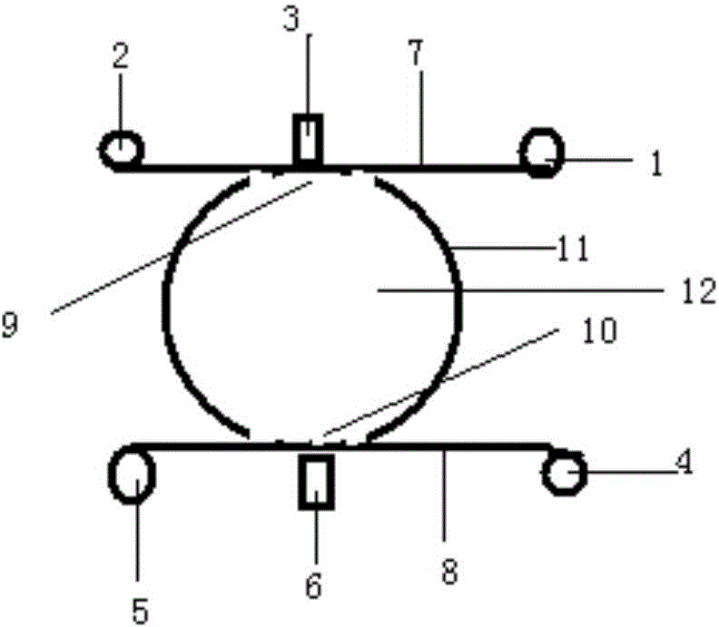
[0015] exist figure 1 Among them, the upper film rotating shaft 1 is connected with the above rotating shaft 2 through the upper film 7, and the infrared sensor 3 passes through the upper film 7, the upper opening 9, the sampling flue 12, the lower opening 10, and the lower film 8, and is the same as the infrared light-emitting tube 6 The upper opening 9 and the lower opening 10 are connected with the sampling flue wall 11, and the lower membrane rotating shaft 4 is connected with the lower membrane driven shaft 5 through the lower membrane 8.

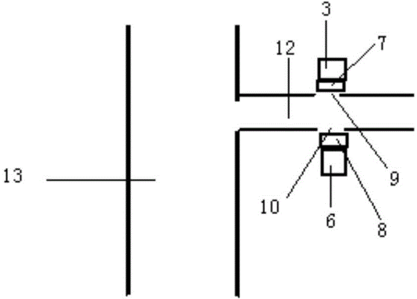
[0016] exist figure 2 In the shown embodiment, the sampling flue 12 is connected to the flue 13, and the infrared sensor 3 is connected to the infrared light-emitting tube 6 through the upper film 7, the upper opening 9, the sampling flue 12, the lower opening 10, and the lower film 8.

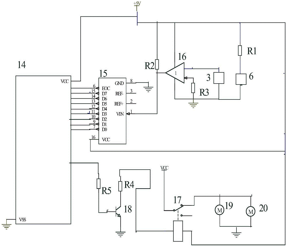
[0017] exist image 3 In the shown embodiment, the infrared light-emitting tube 6 is connected with the resistor R1, the infrared sensor 3 is conne...


PUM


Abstract

The invention relates to a dust sensor based on a continuously changing barrier layer. It belongs to the field of electronic technology. The main technical problem it solves is to overcome the insufficiency of the existing photoelectric sensors that directly contact the smoke and dust. It consists of upper film rotation shaft, upper slave rotation shaft, infrared sensor, lower film rotation shaft, lower film driven shaft, infrared light-emitting tube, upper film, lower film, upper opening, lower opening, sampling flue wall, sampling smoke It is composed of a duct, a flue, a single-chip microcomputer, an analog-to-digital conversion module, an operational amplifier, a relay, a triode, an upper film rotating motor, and a lower film rotating motor. The upper film, the upper opening, the sampling flue, the lower opening and the lower film are connected with the infrared light-emitting tube, the lower film rotating shaft is connected with the lower film driven shaft through the lower film, and the upper film rotating motor and the lower film rotating motor are connected by a relay , transistors, resistors, connected with the microcontroller. It is mainly used in the field of high-voltage electrostatic dust removal.

Description

technical field [0001] The patent of the present invention belongs to the field of electronics, and in particular refers to a dust sensor based on a continuously changing barrier layer. Background technique [0002] Coal combustion used by thermal power enterprises and heating enterprises is one of the important sources of PM2.5, so the control of emissions from these enterprises is an important means to suppress PM2.5. Among the many treatment methods, electrostatic dust removal is an ideal method. Electrostatic precipitator mainly depends on particle charge, and then is removed by adsorption. [0003] The study of electrostatic precipitator is very important to effectively control the content of PM2.5 in the air, but it is very difficult to evaluate the effect of electrostatic precipitator. The reason is that the dust content before and after electrostatic precipitator is very small, and it is very difficult to measure. In the past, the traditional gravimetric method ne...

Claims


Application Information

Patent Timeline
IPC IPC(8): G01N15/06
Inventor 魏胜非
Owner NORTHEAST NORMAL UNIVERSITY
Learn More