
Metal-working machine capable of achieving automatic tool changing

A technology for metal processing and automatic tool change, which is applied in the direction of metal processing machinery parts, metal processing equipment, manufacturing tools, etc., can solve the problems of increasing volume and cost, increasing the complexity of equipment, etc., and achieves easy control and realization, powerful functions, high concentration effect

Inactive Publication Date: 2016-11-23
DEYANG HONGYUAN ELECTROMECHANICAL ENG
View PDF1 Cites 4 Cited by
  • Summary
  • Abstract
  • Description
  • Claims
  • Application Information

AI Technical Summary

Problems solved by technology

[0002] Metal processing mainly uses turning, planing, milling, boring and other processing processes to process metal raw materials into the required structure, but the commonly used processing machine tools can usually only complete one processing at a time, and the processing of a piece of metal often needs to be constantly replaced. For machine tools, in order to complete multiple processing processes on the same platform at the same time, there are also some technical solutions for integrating different processing tools into one processing platform in the prior art, such as the publication number CN201371405, and the publication time is December 30, 2009. The Chinese utility model patent document titled "Special Machine Tool for Grinding and Polishing Integrated Silicon Ingot Processing" discloses a special machine tool that can effectively improve surface processing quality, improve processing efficiency, eliminate environmental pollution, and reduce cost, the technical solution adopted by the utility model is: a special machine tool for grinding and polishing integrated silicon block processing, including a bed, a workbench on the bed and a guide rail horizontally arranged on the top of the bed; it is characterized in that the machine tool is also equipped with There is a grinding head and a polishing head; these two grinding heads are slidably positioned on the guide rail through the slider, and are driven by a traction mechanism for lateral movement, but in this technology, the movement track of the processing part It can only move in one direction horizontally, and it uses different tools on the same slide, which will increase the complexity of the equipment, and greatly increase the volume and cost

Method used


Image

  • Metal-working machine capable of achieving automatic tool changing

Examples


Embodiment 1

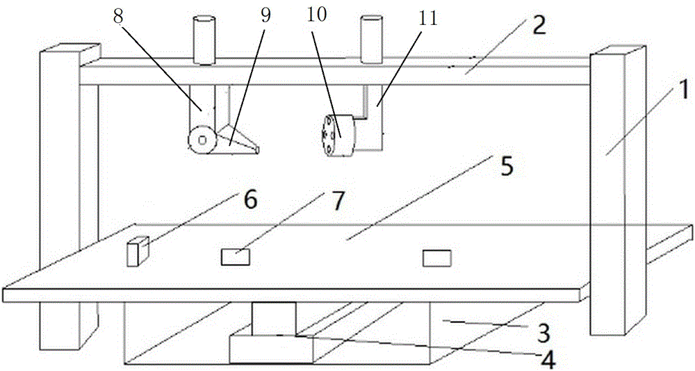
[0020] like figure 1 , an automatic tool-changing metal processing machine tool, including a control mechanism, a gantry and a processing table, the gantry includes two columns 1 and a beam 2, and the beam 2 is provided with a monorail swing arm type automatic tool-changing metal processing mechanism, so The single-track swing arm type automatic tool change metal processing mechanism includes a rotary arm assembly, a tool storage assembly and a track. The rotary arm assembly and the tool storage assembly are slidably arranged on the track. The rotary arm assembly includes a fixed arm 8 connected by a rotating shaft structure and The swing arm 9 is provided with a cutter driver at the front end of the swing arm 9, and a cutter holder is arranged at the front end of the cutter driver. The rotating shaft structure includes a rotating shaft and a driving motor. With the rotary drive motor, the rotary tool rest 10 is provided with a plurality of slots for placing knives at interval...

Embodiment 2

[0023] like figure 1 , an automatic tool-changing metal processing machine tool, including a control mechanism, a gantry and a processing table, the gantry includes two columns 1 and a beam 2, and the beam 2 is provided with a monorail swing arm type automatic tool-changing metal processing mechanism, so The single-track swing arm type automatic tool change metal processing mechanism includes a rotary arm assembly, a tool storage assembly and a track. The rotary arm assembly and the tool storage assembly are slidably arranged on the track. The rotary arm assembly includes a fixed arm 8 connected by a rotating shaft structure and The swing arm 9 is provided with a cutter driver at the front end of the swing arm 9, and a cutter holder is arranged at the front end of the cutter driver. The rotating shaft structure includes a rotating shaft and a driving motor. With the rotary drive motor, the rotary tool rest 10 is provided with a plurality of slots for placing knives at interval...

Embodiment 3

[0027] Such as figure 1 , an automatic tool-changing metal processing machine tool, including a control mechanism, a gantry and a processing table, the gantry includes two columns 1 and a beam 2, and the beam 2 is provided with a monorail swing arm type automatic tool-changing metal processing mechanism, so The single-track swing arm type automatic tool change metal processing mechanism includes a rotary arm assembly, a tool storage assembly and a track. The rotary arm assembly and the tool storage assembly are slidably arranged on the track. The rotary arm assembly includes a fixed arm 8 connected by a rotating shaft structure and The swing arm 9 is provided with a cutter driver at the front end of the swing arm 9, and a cutter holder is arranged at the front end of the cutter driver. The rotating shaft structure includes a rotating shaft and a driving motor. With the rotary drive motor, the rotary tool rest 10 is provided with a plurality of slots for placing knives at inter...


PUM


Abstract

The invention discloses a metal-working machine capable of achieving automatic tool changing, and relates to the field of metal machining. The metal-working machine comprises a control mechanism, a portal frame and a machining table. The portal frame comprises two stand columns and a cross beam. The cross beam is provided with a single-rail swing arm type automatic tool changing metal machining mechanism. The machining table comprises a table body, a lifting mechanism arranged inside the table body, and a table plate arranged on the lifting mechanism. An air blower and fixing clips are arranged on the table plate. The single-rail swing arm type automatic tool changing metal machining mechanism, the lifting mechanism and the air blower are controlled by the control mechanism. The metal-working machine can change tools as required in the machining process. Moreover, the heights of workpieces to be machined can be adjusted in time, the machining positions can be changed, and machining scraps can be removed.

Description

technical field [0001] The invention relates to the field of metal processing, in particular to a metal processing machine tool with automatic tool change. Background technique [0002] Metal processing mainly uses turning, planing, milling, boring and other processing processes to process metal raw materials into the required structure, but the commonly used processing machine tools can usually only complete one processing at a time, and the processing of a piece of metal often needs to be constantly replaced. For machine tools, in order to complete multiple processing processes on the same platform at the same time, there are also some technical solutions for integrating different processing tools into one processing platform in the prior art, such as the publication number CN201371405, and the publication time is December 30, 2009. The Chinese utility model patent document titled "Special Machine Tool for Grinding and Polishing Integrated Silicon Ingot Processing" disclos...

Claims


Application Information

Patent Timeline
IPC IPC(8): B23Q1/25B23Q3/06B23Q3/155B23Q11/00
CPCB23Q1/25B23Q3/06B23Q3/155B23Q11/005
Inventor 刘敏赵成杨天桥孙书俊
Owner DEYANG HONGYUAN ELECTROMECHANICAL ENG
Learn More