Convex closure structure

A convex hull and bottom plate technology, applied to the circuit layout on the support structure, electrical equipment structural parts, electrical components, etc., can solve problems such as deformation of the back plate 4

Inactive Publication Date: 2011-10-05
AU OPTRONICS (SUZHOU) CORP LTD +1
View PDF0 Cites 0 Cited by
  • Summary
  • Abstract
  • Description
  • Claims
  • Application Information

AI Technical Summary

Problems solved by technology

However, the manufacturing process of stamping the back plate 4 may cause deformation of the back plate 4 due to the stamping pressure path or the stamping position.
[0004] Therefore, the design of the conventional convex element on the backplane of the electronic device needs to be improved.

Method used


Image

  • Convex closure structure
  • Convex closure structure
  • Convex closure structure

Examples


Embodiment Construction

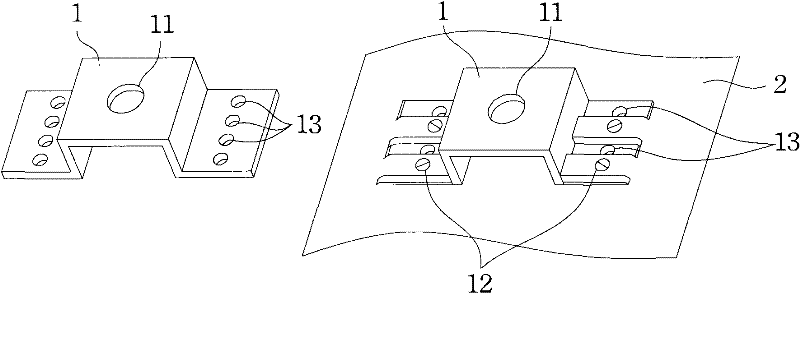
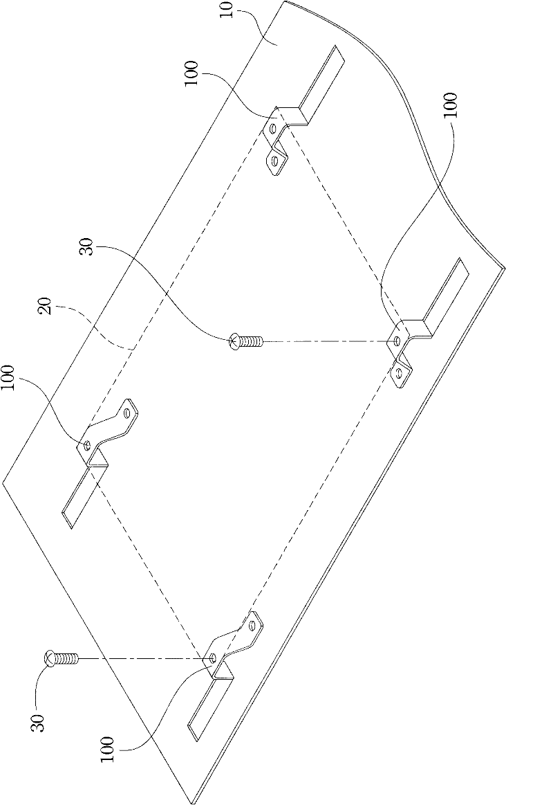
[0043] With reference figure 2 , Is a schematic diagram of the location of the convex hull structure of the present invention. The convex hull structure 100 proposed in the present invention is arranged on the back plate 10 of the electronic device, corresponding to the position of the locking screw 30 of the external element 20, and can be used for locking the external element 20 on the back plate 10 of the electronic device.

[0044] With reference Figure 3A , 3B , Is a schematic diagram of Embodiment 1 of the convex hull structure of the present invention. The convex hull structure 100 of the present invention is composed of at least a bottom plate 110, a bending piece 120, a fastener 130, and a fastener hole 140.

[0045] Such as Figure 3A As shown, the bottom plate 110 has an upper surface 111. The bent piece 120 is a long plate cut at a specific position of the bottom plate 110 and connected to the bottom plate 110 with a connecting end 121. The bent piece 120 is bent ou...


PUM


Abstract

The invention relates to a convex closure structure, which consists of a bottom plate, a bending sheet, a buckling piece and a buckling hole. The bending sheet cuts the bottom plate and is bent out of the bottom plate; a locking hole part and an abutting part are reflexed from the upper surface towards the bottom plate; the abutting part abuts with the bottom plate; the abutting part and the bottom plate are mutually buckled through the buckling piece and the buckling hole; and the abutting part of the bending sheet is buckled and fixed on the bottom plate.

Description

Technical field [0001] The present invention relates to a convex hull structure, in particular to a convex hull structure on a back plate of an electronic device. Background technique [0002] The convex hull on the backplane of the conventional electronic device, such as Figure 1A As shown, by adding a separate convex element 1 to the back plate 2 of the electronic device, for example, screws 12 are passed through the positioning holes 13 on both sides of the convex element 1 to lock the convex element 1 to the back. The board 2 is assembled into a convex hull structure on the back board 2 of the electronic device. A screw hole 11 is provided on the convex portion of the convex hull element 1 to fix external components. However, in addition to the additional installation of the convex-hull element 1 on the back plate 2 in this design, a special mold for making the convex-hull element 1 must also be designed. [0003] The convex hull on the backplane of another conventional elect...

Claims


Application Information

Patent Timeline
Patent Type & Authority Patents(China)
IPC IPC(8): H05K7/12
CPCH05K7/142
Inventor 沈冬明
Owner AU OPTRONICS (SUZHOU) CORP LTD
Why Eureka
Try Eureka