Multifilament and braid
A technology of braiding and single yarn, which is applied in the direction of braiding, spinning solution preparation, filament/thread forming, etc., can solve the problems of low wear resistance, easy to change physical properties, etc., and achieve small changes in mechanical properties , The amount of fluff is reduced, and the effect of excellent wear resistance
- Summary
- Abstract
- Description
- Claims
- Application Information
AI Technical Summary
Problems solved by technology
Method used
Image

Examples
Embodiment 1-1
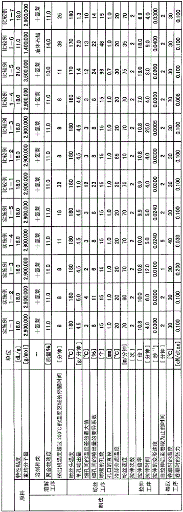
[0197] A dispersion of ultra-high molecular weight polyethylene and decalin having an intrinsic viscosity of 18.0 dL / g, a weight average molecular weight of 2,900,000, and a peak melting point of 134° C. was prepared so that the polyethylene concentration was 11.0% by mass. Use an extruder to set the residence time in the temperature range of 205°C to 8 minutes, make a solution of this dispersion, and spray the polyethylene solution from the spinneret in a single hole at a spinneret surface temperature of 180°C. 4.5g / min sprayed. The number of orifices formed in the spinneret is 15, and the diameter of the orifices is The fine holes (one end of the orifice) for filament ejection formed on the surface of the spinneret are shielded so as not to be in direct contact with the outside air. The plates are shielded from exposure to outside air. The distance between the shielding plate and the pore closest to the shielding plate was set to 40 mm, and the distance between the shield...
Embodiment 1-2
[0199] In embodiment 1-1, the single hole ejection amount of polyethylene solution is set as 5.0g / min, the distance with the pore farthest from the shielding plate is set as 80mm, and the difference between the maximum temperature and the minimum temperature of the pore The difference is set to 4°C, the coefficient of variation CV" of the ejection amount of each pore is set to 11%, the spinning speed is set to 60m / min, and the draw ratio in hot air at 150°C is set to 2.5 times (total The stretching ratio is set to 10.0 times), the total stretching time is set to 6 minutes, and the deformation speed during stretching is set to 0.0200 seconds -1 , except that it was carried out in the same manner as in Example 1-1 to obtain a multifilament. The production conditions of the multifilaments are shown in Table 1, and the physical properties and evaluation results of the obtained multifilaments are shown in Table 2.
Embodiment 1-3
[0201] In Example 1-1, the distance from the pore farthest from the shielding plate was set to 45mm, the difference between the highest temperature and the lowest temperature of the pore was set to 2°C, and the coefficient of variation of the discharge amount of each pore was CV" is set to 6%, the total stretching time is set to 12 minutes, and the deformation speed during stretching is set to 0.0100 seconds -1 A multifilament was obtained in the same manner as in Example 1-1, except that the tension at the time of coiling was 0.200 cN / dtex, and the time from the start of stretching to coiling was 1 minute. The production conditions of the multifilaments are shown in Table 1, and the physical properties and evaluation results of the obtained multifilaments are shown in Table 2.
PUM
| Property | Measurement | Unit |
|---|---|---|
| linear density | aaaaa | aaaaa |
| heat shrinkage ratio | aaaaa | aaaaa |
| heat shrinkage ratio | aaaaa | aaaaa |
Abstract
Description
Claims
Application Information
 - Generate Ideas
- Intellectual Property
- Life Sciences
- Materials
- Tech Scout
- Unparalleled Data Quality
- Higher Quality Content
- 60% Fewer Hallucinations
Browse by: Latest US Patents, China's latest patents, Technical Efficacy Thesaurus, Application Domain, Technology Topic, Popular Technical Reports.
© 2025 PatSnap. All rights reserved.Legal|Privacy policy|Modern Slavery Act Transparency Statement|Sitemap|About US| Contact US: help@patsnap.com