Eureka AIR delivers breakthrough ideas for toughest innovation challenges, trusted by R&D personnel around the world.

Pneumatic tire

A pneumatic tire, tire circumferential technology, applied in the direction of pneumatic tires, tire parts, tire tread/tread pattern, etc., can solve the problems of reduced stiffness, poor noise performance, and low tread stiffness, etc., to achieve improvement Noise performance, improvement of drainage performance, effect of reducing exterior noise

Active Publication Date: 2016-11-16
YOKOHAMA RUBBER CO LTD
View PDF6 Cites 19 Cited by
  • Summary
  • Abstract
  • Description
  • Claims
  • Application Information

AI Technical Summary

Problems solved by technology

However, this method has the following problems: since the rigidity of the land portion formed on the tread is lowered, it is difficult to ensure the dry performance, and the noise performance is also deteriorated.
[0005] However, the structure of Patent Document 1 has the following problem: in order to ensure the drainage performance, a part of the lug grooves communicates with both adjacent two main grooves, but this part of the lug grooves is especially on the outer side when mounted on a vehicle. The main groove is open, so the noise performance cannot be sufficiently improved; in addition, this part of the lug groove also forms a block row, resulting in low tread rigidity, which cannot sufficiently ensure dry performance
In this regard, it is also considered to make this part of the lug groove not open relative to the main groove on the outside when it is installed on the vehicle, but if only this simple modification is adopted, the shape and arrangement of the lug groove will lose the balance , leading to the inability to obtain the dry performance, wet skid resistance, and noise performance that can be obtained by the structure of Patent Document 1

Method used


Image

  • Pneumatic tire
  • Pneumatic tire
  • Pneumatic tire

Examples


Embodiment Construction

[0027] Hereinafter, the configuration of the present invention will be described in detail with reference to the drawings.

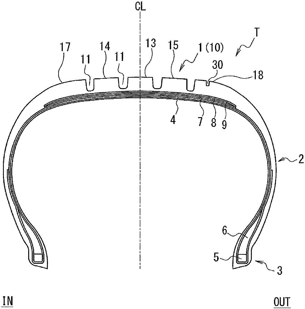
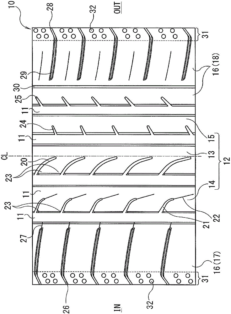
[0028] exist figure 1In the above, the installation direction of the pneumatic tire T on the vehicle is specified, the symbol IN indicates that when installed on the vehicle, it is located on the inner side of the vehicle (hereinafter referred to as the vehicle inner side), and the symbol OUT indicates that when installed on the vehicle On the outer side of the vehicle (hereinafter referred to as the vehicle outer side), the symbol CL denotes the tire equator. This pneumatic tire T is composed of a tread portion 1 , a sidewall portion 2 , and a bead portion 3 . A ply 4 is interposed between a pair of left and right bead portions 3 . The carcass layer 4 includes a plurality of reinforcing cords extending in the radial direction of the tire, and is folded from the inner side to the outer side of the tire around the bead core 5 arranged in each bead porti...


PUM


Abstract

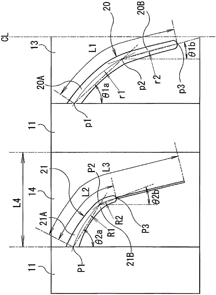
Provided is a pneumatic tire enabling an increase in noise performance while achieving both steering stability on dry road surface and driving performance on wet road surface. In a pneumatic tire (T) including a center land portion (13), an inner central land portion (14), an outer central land portion (15), an inner shoulder land portion (17), and an outer central land portion (18) which are separately formed by at least four main grooves (11), the pneumatic tire having a designated vehicle mount direction, the center land portion (13) is formed with center lug grooves (20) that open only to one of the main grooves (11) on the vehicle inner side, the inner central land portion (14) is formed with inner central lug grooves (21) that open only to another of the main grooves on the vehicle inner side, each of the lug grooves (20, 21) comprising a first inclination portion (20A, 21A) positioned on an opening end side and having a relatively large inclination angle and a second inclination portion (20B, 21B) positioned on a terminal side and having a relatively small inclination angle, and an inner central sipe (22) is formed at the terminal portion of each of the inner central lug grooves (21) terminating within the inner central land portion (14), wherein the relationships L1 ;gt; L2 and L3 ;gt; L4 are satisfied, where L1 is the length of the center lug groove (20), L2 is the length of the inner central lug groove (21), L3 is the sum of the length L2 and the length of the inner central sipe (22), and L4 is the width of the inner central land portion (14).

Description

technical field [0001] The present invention relates to a pneumatic tire, which has at least four main grooves extending along the tire circumferential direction on the tread, and more specifically, relates to a pneumatic tire, which can balance driving stability on dry roads and wet conditions Road performance, and can improve the noise performance. Background technique [0002] In recent years, with the development of road repairs and the improvement of vehicle performance, pneumatic tires are strongly required to be able to balance the driving performance on dry roads (dry performance) and the driving performance on wet roads (wet skid resistance) when driving at high speeds. , and can improve noise performance. [0003] In general, a method for improving wet skid resistance is to form horizontal grooves and sipes extending in the width direction of the tire in addition to the main grooves extending in the tire circumferential direction on the tread surface of the tire t...

Claims


Application Information

Patent Timeline
IPC IPC(8): B60C11/03B60C5/00B60C11/01B60C11/12B60C11/13
CPCB60C11/12B60C11/0304B60C11/0306B60C11/04B60C11/13B60C11/1392B60C2011/0341B60C2011/0372B60C2011/0381B60C2011/0383B60C2011/1209
Inventor 石黑和也
Owner YOKOHAMA RUBBER CO LTD
Why Eureka
Eureka Blog
Learn More