
Adaptive soft-start circuit applied to boost topology switching power supply

A soft-start circuit and switching power supply technology, applied in electrical components, output power conversion devices, etc., can solve the problems of slow rising speed and long start-up time, achieve fast start, eliminate inrush current, and shorten invalid soft-start time. Effect

Inactive Publication Date: 2018-12-18
UNIV OF ELECTRONICS SCI & TECH OF CHINA
View PDF5 Cites 1 Cited by
  • Summary
  • Abstract
  • Description
  • Claims
  • Application Information

AI Technical Summary

Problems solved by technology

The traditional digital soft-start circuit generates a reference voltage that rises slowly at a fixed rate to achieve the purpose of limiting the switch on-duty cycle during the start-up process; however, for boost topology switching power supplies, since their input and output are not isolated, the on-chip After power-on, the output voltage of the switching power supply is charged to be higher than the input voltage at a very fast speed; after the chip is enabled, the soft-start reference voltage begins to rise slowly from zero volts. The reference voltage, the system is in an invalid startup state, until the soft-start reference voltage rises to a sampling value higher than the output voltage, the switching power supply starts to boost the voltage; therefore, the traditional soft-start circuit outputs a soft-start reference that rises at a fixed rate Voltage, its rising speed is usually slow, in order to achieve the purpose of suppressing the inrush current, but also cause the invalid start time to be too long

Method used


Image

  • Adaptive soft-start circuit applied to boost topology switching power supply
  • Adaptive soft-start circuit applied to boost topology switching power supply
  • Adaptive soft-start circuit applied to boost topology switching power supply

Examples


Embodiment Construction

[0020] The present invention will be further described in detail below with reference to the drawings and specific embodiments, but the present invention is not limited thereto.

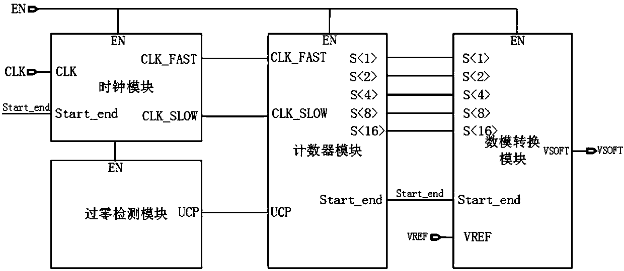
[0021] This embodiment provides an adaptive soft-start circuit applied to a boost topology switching power supply. The system schematic diagram is as figure 1 As shown, the soft start circuit is composed of a clock module, a zero-crossing detection module, a counter module, and a digital-to-analog conversion module; the clock module uses the input basic clock CLK to generate a high-frequency clock CLK_FAST (fast clock) and a low-frequency clock CLK_SLOW (slow clock) ) Input to the counter module; the zero-crossing detection module generates a control signal UCP according to the magnitude of the energy storage inductor current and provides it to the counter module. When the inductor current is lower than the preset threshold I 1 When the UCP output is "1," when the inductor current is higher than or equal ...


PUM


Abstract

The invention belongs to the technical field of switching power supply soft start, and provides an adaptive soft start circuit applied to a boost topology switching power supply, which is used to overcome the problem of too long invalid start time of the existing soft start circuit; including a clock module and a zero-crossing detection module , counter module and digital-to-analog conversion module, the clock module generates two clock signals, fast and slow, to input the counter module; the zero-crossing detection module generates a control signal to the counter module according to the size of the energy storage inductor current; the counter module selects the fast clock signal according to the control signal The clock signal or slow clock signal is used as the counting clock to realize counting at different speeds and output binary counting values; the digital-to-analog conversion module converts the binary counting values ​​output by the counter into analog signals, and outputs soft-start reference voltages that rise in steps. The present invention introduces a zero-crossing detection control signal, self-adaptively adjusts the rising rate of the soft-start reference voltage, and greatly shortens the invalid soft-start time of the boost topology switching power supply.

Description

Technical field [0001] The invention belongs to the technical field of switching power supply soft start, and particularly relates to an adaptive soft start circuit applied to a boost topology switching power supply. Background technique [0002] In recent years, with the continuous growth of portable electronic products in the fields of communications, computers, and consumer electronics, the demand for power management chips is also on the rise. DC-DC switching power supplies have a wide input voltage range and wide load range. It has outstanding efficiency performance and is widely used. As an important topology of switching power supply, Boost boost structure has been widely used in various switching power supply chips with the widespread use of low-voltage power supplies such as lithium batteries. The PWM switching power supply works by converting the error signal into a duty cycle control signal to drive the power switch. During the start-up phase, the error amplifier is i...

Claims


Application Information

Patent Timeline
Patent Type & Authority Patents(China)
IPC IPC(8): H02M1/36
CPCH02M1/36
Inventor 宁宁段开锋俞德军梁孝亿
Owner UNIV OF ELECTRONICS SCI & TECH OF CHINA
Learn More