
Vertical laminated busbar-based converter module

A technology of laminated busbars and converters, which is applied in the direction of output power conversion devices, electrical components, cooling/ventilation/heating transformation, etc., can solve the problem of reducing the inductance value of IGBT power devices to peak absorption capacitors, and shortening peak absorption capacitors The distance from the IGBT power device and other issues can be avoided to avoid excessive stray inductance, compact structure, and reduce the inductance value.

Active Publication Date: 2016-11-16
ZHUHAI HENGQIN JIUYUAN POWER ELECTRONICS SCI &TECH CO LTD
View PDF5 Cites 5 Cited by
  • Summary
  • Abstract
  • Description
  • Claims
  • Application Information

AI Technical Summary

Problems solved by technology

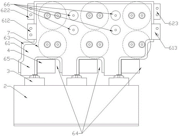
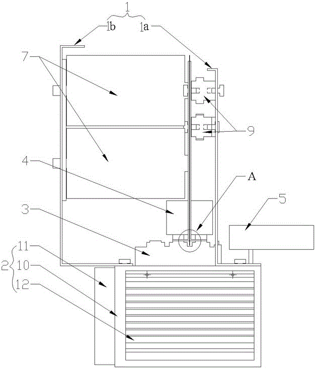
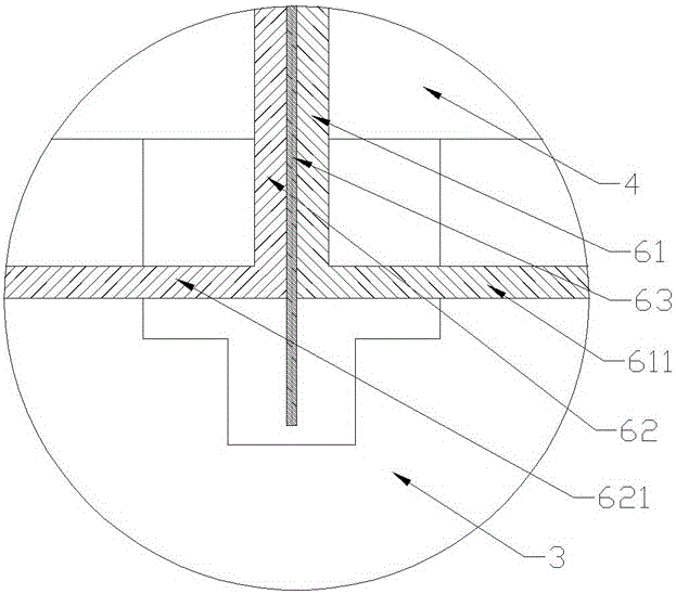
[0006] It can be seen from the above scheme that the present invention arranges the IGBT power device on the heat dissipation system, the peak absorbing capacitor is connected to the positive and negative poles of the IGBT power device through the positive and negative poles, and the three-phase half-bridge DC busbar is vertically arranged on the IGBT power device and the input positive pole of the positive busbar and the input negative pole of the negative busbar are respectively connected to the positive pole and negative pole of the IGBT power device, and the positive pole and negative pole of the IGBT power device are connected between the two ends of the three-phase half-bridge DC busbar. The side is symmetrically arranged, and its structure is compact and the layout is reasonable. Compared with the prior art, the three-phase half-bridge DC busbar is vertically connected to the IGBT power device, and the positive busbar and negative busbar are connected to the positive and negative poles of the IGBT power device. The distance is equal to achieve the effect of current sharing; the three-phase half-bridge DC busbar is composed of a positive busbar and a negative busbar that are symmetrically superimposed on each other, and an insulation is provided between the positive busbar and the negative busbar layer, where the positive busbar and the negative busbar are overlapped and laminated, and an insulating layer is added in the middle, so as to realize the large-area overlap of the DC busbar, avoid the excessive distribution of stray inductance of the busbar, and improve its electrical performance; in addition, Set the peak snubber capacitor at the capacitance window and make its positive and negative poles directly connected to the positive and negative poles of the IGBT power device, which shortens the distance between the peak snubber capacitor and the IGBT power device, and does not require PCB connection boards or other wiring inputs , the whole structure is more concise, and the inductance value from the IGBT power device to the peak absorbing capacitor is reduced; in addition, the DC support capacitor is set on the three-phase half-bridge DC busbar, and the connection of the three-phase half-bridge DC busbar avoids the IGBT The problem of excessive board-level impedance caused by the PCB board or connecting wire between the power device and the DC support capacitor; each device in the module is easy to assemble and disassemble, its maintenance is convenient, and the maintenance cost is low; more importantly, Yes, through the setting of the three-phase half-bridge DC busbar, high voltage, high current, and high power conversion can be realized, and its current carrying capacity is greatly improved

Method used


Image

  • Vertical laminated busbar-based converter module
  • Vertical laminated busbar-based converter module
  • Vertical laminated busbar-based converter module

Examples


Embodiment Construction

[0030] Such as Figure 1 to Figure 7As shown, in this embodiment, the module includes a support frame 1, a heat dissipation system 2, three IGBT power devices 3, three peak absorbing capacitors 4, a drive unit 5, a three-phase half-bridge DC busbar 6 and six DC Supporting capacitors 7 , the six DC supporting capacitors 7 are film capacitors and evenly distributed on the three-phase half-bridge DC busbar 6 . The support frame 1 includes a front support 1a and a rear support 1b, the front support 1a and the rear support 1b are vertically arranged on the heat dissipation system 2 and are located on both sides of the three-phase half-bridge DC busbar 6, in The three-phase half-bridge DC busbar 6 is also provided with four mechanical holes 66, one end of the DC support capacitor 7 is connected to the three-phase half-bridge DC busbar 6, and the other end is fixed to the rear bracket 1b Four insulating columns 9 are arranged between the three-phase half-bridge DC busbar 6 and the f...


PUM


Abstract

The invention aims at providing a vertical laminated busbar-based converter module which is compact in structure, reasonable in arrangement, high in safety and reliability, convenient to maintain and good in electrical property. According to the vertical laminated busbar-based converter module, a three-phase half-bridge DC busbar comprises symmetrically superimposed positive busbar and negative busbar; an insulating layer is arranged between the positive busbar and the negative busbar; an input positive electrode of the positive busbar and an input negative electrode of the negative busbar are correspondingly connected with a positive electrode and a negative electrode of an IGBT power device; the positive electrode and the negative electrode of the IGBT power device are symmetrically arranged at two sides of the three-phase half-bridge DC busbar; capacitance windows which are equal to peak absorption capacitors in number are arranged in the lower side edge of the three-phase half-bridge DC busbar; the peak absorption capacitors are located at the capacitance windows and the positive electrodes and the negative electrodes of the peak absorption capacitors are correspondingly connected with the positive electrode and the negative electrode of the IGBT power device respectively; and a DC support capacitor is connected to the three-phase half-bridge DC busbar. The vertical laminated busbar-based converter module can be applied to the field of power equipment.

Description

technical field [0001] The invention relates to electric equipment, in particular to a converter module based on vertically installed laminated busbars. Background technique [0002] At present, the research on new energy converters in China is still in its infancy, and the configuration of power units only considers the appearance and seldom pursues excellent performance. It is balanced and matched with the power expansion unit. Due to the limitation of IGBT over-current capability, the parallel performance cannot be guaranteed in the place where parallel connection is required, and it is difficult to realize the high-current converter produced by the current power battery, and the application in the charger or power battery test place is limited. [0003] At present, high-power converters generally use a single converter bridge arm as a power unit module, which is assembled through external connections of the modules. At the same time, a single module is equipped with a ...

Claims


Application Information

Patent Timeline
IPC IPC(8): H02M1/00H05K7/20
CPCH02M1/00H05K7/20
Inventor 屈世磊
Owner ZHUHAI HENGQIN JIUYUAN POWER ELECTRONICS SCI &TECH CO LTD
Learn More