Novel composite gate valve assembly
A compound, gate valve technology, applied in sliding valves, valve details, valve devices, etc., can solve problems such as dirt accumulation, pressure drop and increase time, local pressure, etc.
- Summary
- Abstract
- Description
- Claims
- Application Information
AI Technical Summary
Problems solved by technology
Method used
Image

Examples
Embodiment 1
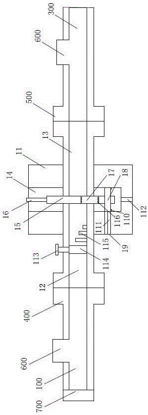
[0030] A new composite gate valve assembly includes a water inlet pipe 100, a gate valve 200 and an outlet pipe 300, the water inlet pipe 100 and the gate valve 200 are fixedly connected by a high-pressure threaded flange 400, and the gate valve 200 and the outlet pipe 300 Fixedly connected by the butt welding flange 500, the outlet pipe 300 and the water inlet pipe 100 are provided with a pipe sight glass 600; A central large hole and a central small hole located around the central large hole are provided, and the diameter of the central large hole is 1.5-2.8 times that of the central small hole; the gate valve 200 includes a valve body 11, and the two ends of the valve body 11 A water inlet channel 12 and a water outlet channel 13 are provided, a cavity 14 is arranged between the water inlet channel 12 and the water outlet channel 13, a gate 15 is arranged in the cavity 14, and the top of the gate 15 is provided with The switch handwheel 16, the gate plate 15 is provided wit...
Embodiment 2
[0032]A new composite gate valve assembly includes a water inlet pipe 100, a gate valve 200 and an outlet pipe 300, the water inlet pipe 100 and the gate valve 200 are fixedly connected by a high-pressure threaded flange 400, and the gate valve 200 and the outlet pipe 300 Fixedly connected by the butt welding flange 500, the outlet pipe 300 and the water inlet pipe 100 are provided with a pipe sight glass 600; A central large hole and a central small hole located around the central large hole are provided, and the diameter of the central large hole is 1.5-2.8 times that of the central small hole; the gate valve 200 includes a valve body 11, and the two ends of the valve body 11 A water inlet channel 12 and a water outlet channel 13 are provided, a cavity 14 is arranged between the water inlet channel 12 and the water outlet channel 13, a gate 15 is arranged in the cavity 14, and the top of the gate 15 is provided with The switch handwheel 16, the gate plate 15 is provided with...
Embodiment 3
[0042] A new composite gate valve assembly includes a water inlet pipe 100, a gate valve 200 and an outlet pipe 300, the water inlet pipe 100 and the gate valve 200 are fixedly connected by a high-pressure threaded flange 400, and the gate valve 200 and the outlet pipe 300 Fixedly connected by the butt welding flange 500, the outlet pipe 300 and the water inlet pipe 100 are provided with a pipe sight glass 600; A central large hole and a central small hole located around the central large hole are provided, and the diameter of the central large hole is 1.5-2.8 times that of the central small hole; the gate valve 200 includes a valve body 11, and the two ends of the valve body 11 A water inlet channel 12 and a water outlet channel 13 are provided, a cavity 14 is arranged between the water inlet channel 12 and the water outlet channel 13, a gate 15 is arranged in the cavity 14, and the top of the gate 15 is provided with The switch handwheel 16, the gate plate 15 is provided wit...
PUM
 Abstract
Description
Claims
Application Information
 - R&D
- Intellectual Property
- Life Sciences
- Materials
- Tech Scout
- Unparalleled Data Quality
- Higher Quality Content
- 60% Fewer Hallucinations
Browse by: Latest US Patents, China's latest patents, Technical Efficacy Thesaurus, Application Domain, Technology Topic, Popular Technical Reports.
© 2025 PatSnap. All rights reserved.Legal|Privacy policy|Modern Slavery Act Transparency Statement|Sitemap|About US| Contact US: help@patsnap.com