Passive type building energy conservation integration system

A passive building and building structure technology, applied in construction, building materials, building components, etc., can solve problems such as affecting construction speed, hidden dangers, and slow project progress.

Inactive Publication Date: 2016-11-16
HUNAN BDF ENERGY SAVING TECH +2
View PDF13 Cites 1 Cited by
  • Summary
  • Abstract
  • Description
  • Claims
  • Application Information

AI Technical Summary

Problems solved by technology

[0007] The purpose of the present invention is to promote the process of housing industrialization, use the passive building energy-saving integrated system, improve the existing frame shear wall structure system; make full use of the advantages of factory industrialization, prefabricate and produce prefabricated prefabricated wall panel components, and solve the problems existing in the existing system. Construction, environmental protection, weight, cost, work efficiency and other issues; the overall force of the building structure is solved by pouring reinforced concrete on site, which organically combines industrial production of prefabricated assembled wall panels and assembled cavity floors with on-site poured reinforced concrete , to optimize the existing frame-shear wall structure system technology, transform and upgrade the existing prefabricated frame-shear wall structure system, and update it; solve the problems of poor controllability of overall on-site pouring, strong implementation technology, and on-site construction in the existing system Cause environmental pollution, heavy weight, high construction cost, slow progress of the project, exempt a large number of building templates and steel supports, resulting in long formwork time and affecting the construction speed; using steel supports and its structural parts are vulnerable to safety hazards and difficult to form industrialization Production and other issues

Method used


Image

  • Passive type building energy conservation integration system
  • Passive type building energy conservation integration system
  • Passive type building energy conservation integration system

Examples


Embodiment Construction

[0027] The invention will be further described below in conjunction with the accompanying drawings.

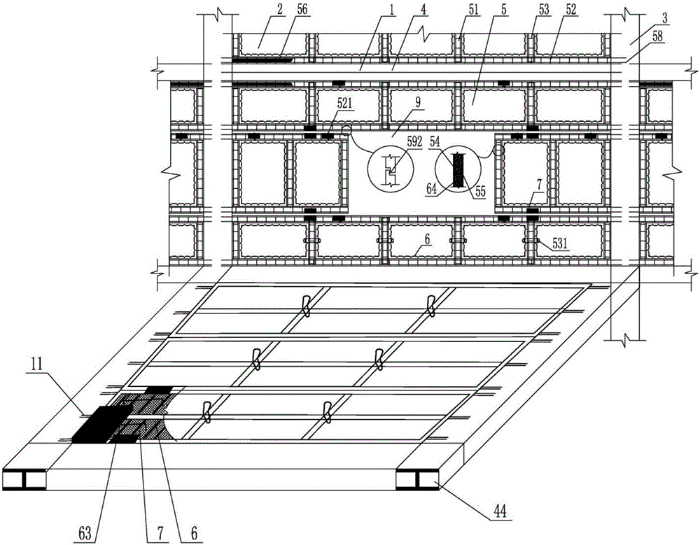
[0028] figure 1 It is a plan view of the passive building energy-saving integrated system of the present invention. When the present invention is implemented, it is a prefabricated prefabricated wall panel component 2 that will be produced on the factory assembly line; Go to the molding workshop and the ribbed steel bar and filling body workshop; install the vertical formwork on the bottom formwork to form the open base formwork of the required specifications and models, and place rib beam reinforcement, ribbed steel mesh, Willow mouth molds, pipes between rib beams, etc.; then transfer the bottom mold system with surrounding rails to the pouring workshop. The computer automatically mixes the proportions of cement, sand, and stone, and then sends it to the mixing station to add water and mix it into concrete. The slump is controlled Within 200mm; start the vibrating table, po...


PUM


Abstract

The invention provides a passive building energy-saving integrated system, which includes a main body of a building structure, a floor slab in a horizontal direction, a wall panel in a vertical direction, and doors and windows; the main body of the building structure is a reinforced concrete structure or a steel-concrete composite structure; It is a prefabricated cavity floor or a cast-in-place reinforced concrete cavity floor; the prefabricated frame member of the prefabricated cavity floor is manufactured in the factory, and the upper flange plate is poured on site; the wall panels in the vertical direction are made of prefabricated wall panels The components are assembled; the assembled prefabricated wall panel components are produced by the factory according to the geometric dimensions and specifications determined by decomposing the design drawings; the assembled prefabricated wall panel components have self-insulation function; Formed when wall panel members are assembled. The assembled prefabricated wall panel components produced by the above process have strong integrity, reasonable structure, high quality standard, controlled process, and good self-insulation and sound insulation performance.

Description

technical field [0001] The invention relates to a housing industrialization system technology, in particular to a passive building energy-saving integrated system technology. Background technique [0002] In the 1980s, the production of concrete prefabricated components in my country was in a stage of great development. In the process of housing construction, the country adopted hollow prefabricated slab structures, large slab structures, cast-in-place concrete structures, cast-in-place concrete hollow floor slab structures, and cast-in-place frame shear forces. Wall structure, etc. With the process of housing industrialization, steel-concrete composite structure and steel-concrete composite cavity floor structure system have been developed rapidly. [0003] For example, the ZL98231113.3 concrete thin-walled cylindrical member declared by the inventor is made into a sealed cylindrical filling body, which provides a tubular hollow filling body for the realization of the cast-i...

Claims


Application Information

Patent Timeline
IPC IPC(8): E04B1/00E04B1/02E04B1/04E04B5/26
CPCE04B1/00E04B1/02E04B1/04E04B5/26E04B2103/02
Inventor 王本淼尚仁杰扶长生韩爱兴王海崴贾英杰程志军王晓锋马锋
Owner HUNAN BDF ENERGY SAVING TECH
Why Eureka
Try Eureka