
A welding void suppression device and its working method

A technology for suppressing devices and voids, applied in auxiliary devices, manufacturing tools, welding equipment, etc., can solve the problems of not being suitable for large-scale production, harsh and complex implementation conditions, etc., to improve the efficiency of water vapor diffusion, improve safety, and prevent welding voids inhibitory effect

Active Publication Date: 2018-04-03
YANGZHOU YANGJIE ELECTRONIC TECH CO LTD
View PDF11 Cites 0 Cited by
  • Summary
  • Abstract
  • Description
  • Claims
  • Application Information

AI Technical Summary

Problems solved by technology

However, the method is harsh and complicated, and is not suitable for large-scale production

Method used


Image

  • A welding void suppression device and its working method
  • A welding void suppression device and its working method
  • A welding void suppression device and its working method

Examples


Embodiment Construction

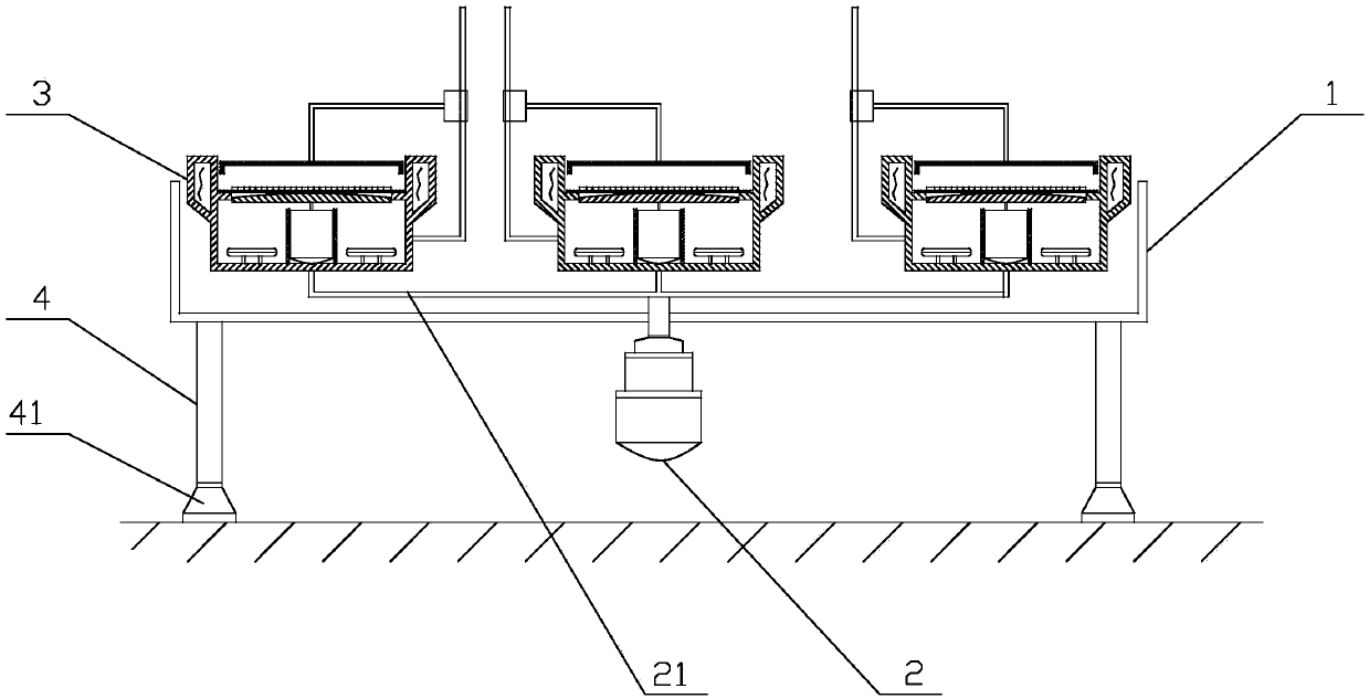
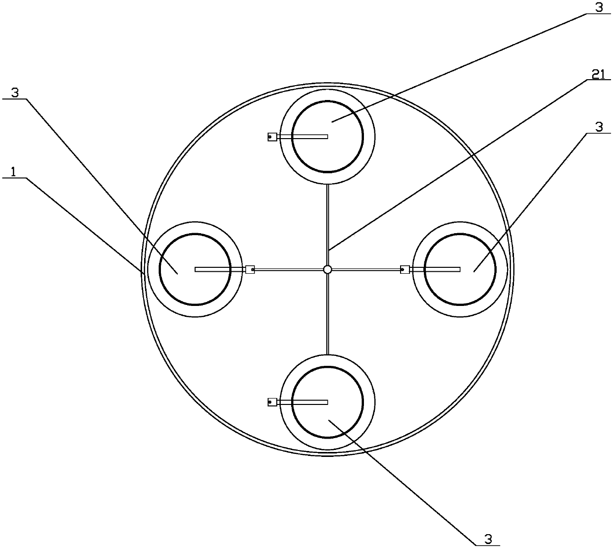
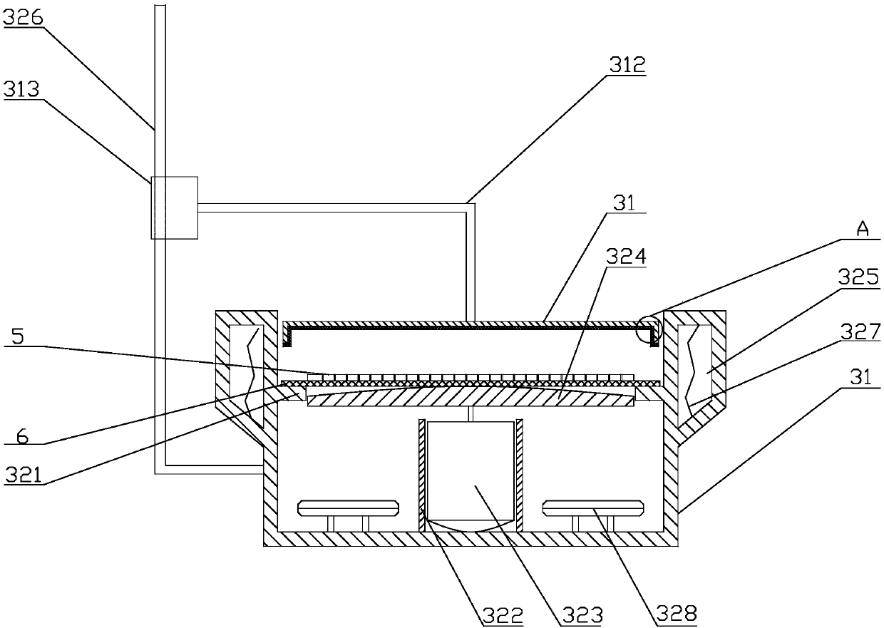
[0033] The present invention as Figure 1-4 As shown, it includes a circular protective bin 1, a stepper motor 2 and four drying bins 3; the center of the protective bin 1 is provided with a circular hole for the shaft of the stepper motor 2 to pass through, and the stepper motor The shaft of 2 passes through the round hole and is fixed on the lower surface of the protective chamber 1; the stepper motor 1 is used to drive the drying chamber to rotate in the protective chamber 2, and the staff can collect and place the wafer 5 (wafer) on the side of the protective chamber 1 Refers to the wafer that has been coated and cut, but the back is still adhered to the blue film), which is convenient and quick, improves work efficiency and reduces work burden. Due to the isolation of the protective compartment, the safety performance is high.

[0034] The four drying bins 3 are respectively equipped with electric heating devices for heating the drying bins 3, thereby heating the wafers ...


PUM


Abstract

The invention provides a weld void restraining device and an operating method thereof and relates to the field of wafer processing, in particular to a device for restraining weld voids in the wafer processing process and an operating method of the device. According to the weld void restraining device and the operating method thereof, the structure is simple, the cost is low, operating steps are simple, and the weld void restraining effect is good. A round hole which can allow a shaft of a stepping motor to penetrate through is formed in the center of a protective bin, and the shaft of the stepping motor penetrates through the round hole and is fixed to the lower surface of the protective bin. Electric heating devices are arranged in four drying bins correspondingly and used for heating the drying bins. The drying bins are connected with the shaft of the stepping motor through a rotary shaft. The rotary shaft is welded to the bottoms of the drying bins. The weld void restraining device and the operating method thereof have the advantages that the structure is simple, production is convenient, the safety performance is good, the cost is low, operating steps are simple, and the weld void restraining effect is good.

Description

technical field [0001] The invention relates to the field of wafer processing, in particular to a device for suppressing welding voids during wafer processing and a working method thereof. Background technique [0002] When using soft solder to solder the bottom of the chip, it is often found that there are large differences in soldering voids for chips provided by different fabs. Under the same packaging technology, the soldering voids of chips from some fabs will exceed the industry standard. The proportion of internal voids is required, resulting in abnormal welding quality. The main causes of soldering voids are: first, the moisture adsorbed on the back of the chip during transportation; second, during the cutting process, the cutting knife needs to be cooled by water, because the dicing tape and the chip are not firmly adhered, and the metal layer structure on the back is sparse, and the water vapor from The side of the chip penetrates into it. [0003] An invention p...

Claims


Application Information

Patent Timeline
Patent Type & Authority Patents(China)
IPC IPC(8): H01L21/67
CPCB23K3/085
Inventor 周理明范永胜王陆委陈雪薛伟徐俊王毅
Owner YANGZHOU YANGJIE ELECTRONIC TECH CO LTD
Learn More