Roots for turbine blades

一种涡轮叶片、涡轮叶的技术,应用在叶片的支承元件、用于弹性流体的泵送装置的部件、非变容式泵等方向,能够解决涡轮叶根不再紧密地贴靠、松动等问题,达到短开始运行时间、快负荷变换、小化塑性变形的倾向的效果

Inactive Publication Date: 2017-11-14
SIEMENS AG
View PDF7 Cites 0 Cited by
  • Summary
  • Abstract
  • Description
  • Claims
  • Application Information

AI Technical Summary

Problems solved by technology

This leads to the fact that the turbine blade root no longer fits tightly at this point and becomes loose

Method used


Image

  • Roots for turbine blades
  • Roots for turbine blades
  • Roots for turbine blades

Examples


Embodiment Construction

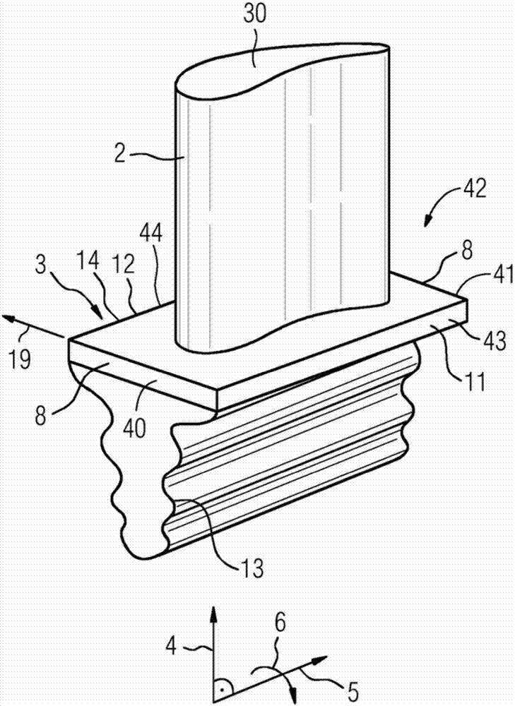
[0032] figure 1 A turbine blade 1 is shown. The turbine blade 1 can be a turbine guide blade or a turbine rotor blade. The turbine blade 1 has an airfoil 2 and a blade root 3 which are arranged along a blade axis 4 . The blade axis 4 corresponds substantially to the elongated configuration of the turbine blade 1 . The blade airfoil 2 is shaped and designed for installation in a fluid machine, in particular a steam turbine. The turbine blade 1 engages in a groove which is not shown in detail. A fluid machine, such as a steam turbine, has a rotor mounted rotatably about an axis of rotation 5 and a housing arranged around the rotor. The grooves are provided on the surface (not shown) in the rotor, the rotor being formed around the axis of rotation 5 . As a result, the rotor rotates in a direction of rotation 6 about the axis of rotation 5 . The blade axis 4 is here formed perpendicular to the axis of rotation 5 . The axis of rotation 5 and the blade axis 4 form a radius su...


PUM


Abstract

The invention relates to a turbine blade (1) having a blade body (2), a blade root (3) and a cover plate (14) between the blade root (3) and the blade body (2), wherein The cover plate (14) has a parallelogram shape (42) with a front side (40) and a back side (41) and a first abutment surface (43) and a second abutment surface (44), wherein the blade body (2) is shaped and has an inflow edge (45) and an outflow edge (46), wherein the inflow edge (45) points toward the front (40) and the outflow edge (46) points toward the rear (41), And wherein the front side (40) has a bend (20) in sections in order to avoid plastic deformation during operation.

Description

technical field [0001] The invention relates to a turbine blade having a blade body and a blade root, wherein the blade root and the blade body are formed along a blade axis, the blade axis being oriented perpendicularly to the axis of rotation, wherein the axis of rotation and the blade axis form a radial surface The blade root also has side surfaces which are formed substantially perpendicular to the radius surface. [0002] Furthermore, the invention relates to a method for producing an arrangement of a turbine blade in a groove of a turbomachine. Background technique [0003] The superordinate concept "fluid machinery" includes water turbines, steam and gas turbines, wind turbines, centrifugal pumps and compressors, and propellers. Common to all these machines is that they are used to extract energy from a fluid to drive other machines, or conversely to deliver energy to a fluid to increase the pressure of said fluid. [0004] A steam turbine as an embodiment of a flui...

Claims


Application Information

Patent Timeline
Patent Type & Authority Patents(China)
IPC IPC(8): F01D5/30F04D29/32
CPCF04D29/322F05D2230/642F05D2240/80F01D5/3038F05D2230/50
Inventor 阿尔明·德拉泽尔
Owner SIEMENS AG
Why Eureka
Try Eureka