


Quick Research
Generate reliable direction feasibility study reports for your R&D in just a few steps.

Technical Q&A
Discover and master advanced knowledge NOW. Basics, ideas, possibilities, all at once.

Find Solutions
As an expert in R&D theories, this can generate solutions to your technical problems instantly.

Evaluate Feasibility
Analyze your overall solution with one click, know your potential R&D risks in advance.

Monitor Landscape
Get weekly tech updates, stay abreast of the latest tech innovations and key insights.
Photovoltaic cell with self-radiating composite cathode buffer layer and preparation method thereof
A cathode buffer layer, composite cathode technology, applied in photovoltaic power generation, semiconductor/solid-state device manufacturing, circuits, etc., can solve the problems of increasing the weight and thickness of the battery, damaging the structure of each layer of the battery, etc., to improve the photoelectric conversion efficiency, increase Effect of electron mobility and high thermal conductivity
- Summary
- Abstract
- Description
- Claims
- Application Information
AI Technical Summary
Problems solved by technology
Method used
Image

Examples
Embodiment 1
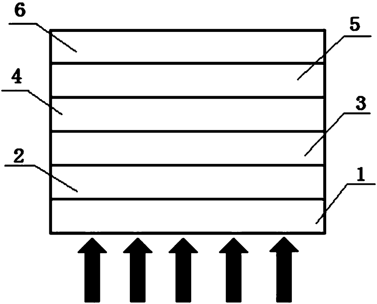
[0035] Such as figure 1 As shown, a photovoltaic cell with a self-heating composite cathode buffer layer adopts an inverted structure, and is arranged in sequence from bottom to top: substrate 1, transparent conductive cathode ITO 2, composite cathode buffer layer 3, photoactive layer 4, anode Buffer layer 5, metal anode 6, the composite cathode buffer layer 3 is composed of cathode buffer layer 31 and heat dissipation grid 32.
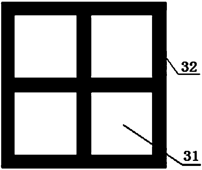
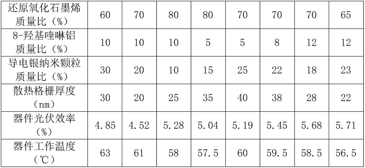
[0036] The structure of the present embodiment composite cathode buffer layer 3 is as follows figure 2 As shown, the heat dissipation grid 32 is in the shape of a square, and the mass percentages of the components in the heat dissipation grid 32 are: 60% of reduced graphene oxide, 10% of 8-hydroxyquinoline aluminum, 30% of conductive silver nanoparticles, The heat dissipation grid 32 has a thickness of 30 nm.
[0037] A method for preparing a photovoltaic cell with a self-radiating composite cathode buffer layer provided in this embodiment is as fo...
Embodiment 2
[0040] Such as figure 1 As shown, a photovoltaic cell with a self-heating composite cathode buffer layer adopts an inverted structure, and is arranged in sequence from bottom to top: substrate 1, transparent conductive cathode ITO 2, composite cathode buffer layer 3, photoactive layer 4, anode Buffer layer 5, metal anode 6, the composite cathode buffer layer 3 is composed of cathode buffer layer 31 and heat dissipation grid 32.
[0041] The structure of the present embodiment composite cathode buffer layer 3 is as follows figure 2 As shown, the heat dissipation grid 32 is in the shape of a square, and the mass percentages of the components in the heat dissipation grid 32 are: 70% of reduced graphene oxide, 10% of 8-hydroxyquinoline aluminum, 20% of conductive silver nanoparticles, The heat dissipation grid 32 has a thickness of 20 nm.
[0042] A method for preparing a photovoltaic cell with a self-radiating composite cathode buffer layer provided in this embodiment is as fo...
Embodiment 3
[0045] Such as figure 1 As shown, a photovoltaic cell with a self-heating composite cathode buffer layer adopts an inverted structure, and is arranged in sequence from bottom to top: substrate 1, transparent conductive cathode ITO 2, composite cathode buffer layer 3, photoactive layer 4, anode Buffer layer 5, metal anode 6, the composite cathode buffer layer 3 is composed of cathode buffer layer 31 and heat dissipation grid 32.
[0046] The structure of the present embodiment composite cathode buffer layer 3 is as follows figure 2 As shown, the heat dissipation grid 32 is in the shape of a square, and the mass percentages of the components in the heat dissipation grid 32 are: 80% reduced graphene oxide, 10% 8-hydroxyquinoline aluminum, 10% conductive silver nanoparticles, The heat dissipation grid 32 has a thickness of 25 nm.
[0047] A method for preparing a photovoltaic cell with a self-radiating composite cathode buffer layer provided in this embodiment is as follows:
...
PUM
| Property | Measurement | Unit |
|---|---|---|
| thickness | aaaaa | aaaaa |
| width | aaaaa | aaaaa |
| thickness | aaaaa | aaaaa |
Abstract
Description
Claims
Application Information
 - R&D Engineer
- R&D Manager
- IP Professional
- Industry Leading Data Capabilities
- Powerful AI technology
- Patent DNA Extraction
Browse by: Latest US Patents, China's latest patents, Technical Efficacy Thesaurus, Application Domain, Technology Topic, Popular Technical Reports.
© 2024 PatSnap. All rights reserved.Legal|Privacy policy|Modern Slavery Act Transparency Statement|Sitemap|About US| Contact US: help@patsnap.com