
Self-adaptive fire-arc-removing relay control method applied to voltage stabilizers

A relay control and self-adaptive technology, applied in control/regulating systems, instruments, regulating electrical variables, etc., can solve the problems of increasing production and procurement, only estimating the approximate position of the zero point, and different operating times, so as to achieve accurate judgment, The effect of improving the control effect, improving the voltage regulation accuracy and the life of the voltage regulator

Active Publication Date: 2016-11-09
ZHEJIANG TTN ELECTRIC
View PDF5 Cites 5 Cited by
  • Summary
  • Abstract
  • Description
  • Claims
  • Application Information

AI Technical Summary

Problems solved by technology

However, there are still many problems in the existing zero point detection technology: firstly, the position of the zero point cannot be accurately captured, and only the approximate position of the zero point can be estimated; secondly, the end point of the action of the relay cannot be accurately controlled to approach the zero point, but an estimated delay is given to the relay. Time value, so that the end point is roughly close to zero; then, the action time of different types of relays is different, and the action time of two relays of the same type is also different, the opening and closing time of the relay are different, the existing technology can only roughly estimate a certain type The action time of the relay cannot be accurately controlled, which also adds a lot of trouble to production and procurement; in addition, there are also problems in the control accuracy and control logic of the relay, which often leads to unsatisfactory voltage stabilization effect

Method used


Image

  • Self-adaptive fire-arc-removing relay control method applied to voltage stabilizers
  • Self-adaptive fire-arc-removing relay control method applied to voltage stabilizers
  • Self-adaptive fire-arc-removing relay control method applied to voltage stabilizers

Examples


Embodiment Construction

[0020] The present invention will be further described in detail below in conjunction with the accompanying drawings and embodiments.

[0021] Such as figure 1 As shown, this embodiment includes a one-way optocoupler zero point detection module, a time delayer group, a relay control module, a relay group, a time counter group, a bidirectional optocoupler zero point detection module and a time comparator group, and the time delayer group, the time counter group, the time comparator group and the relay group are configured in one-to-one correspondence, and they control the relay according to the following steps:

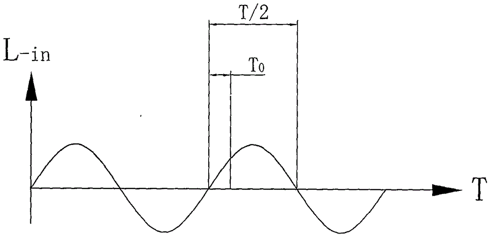
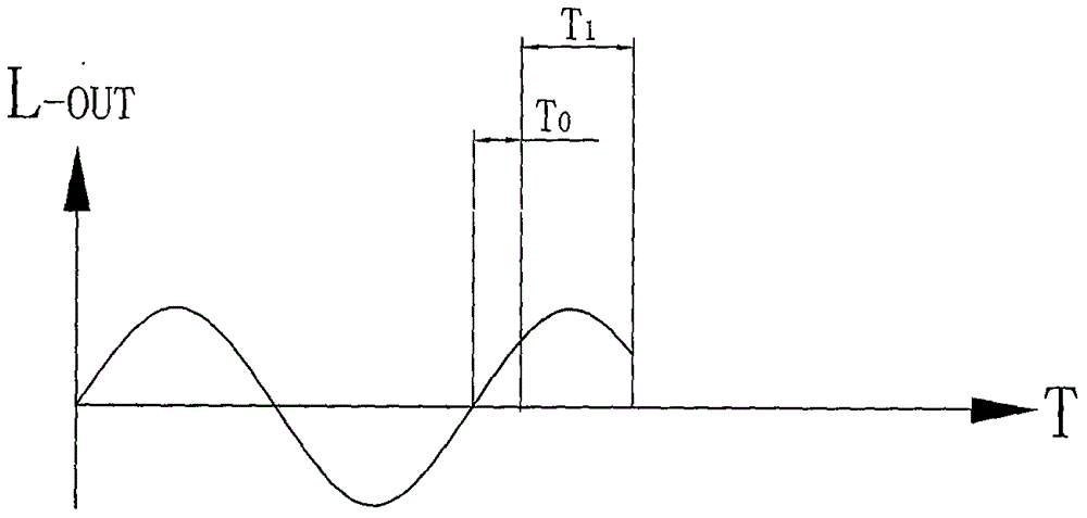
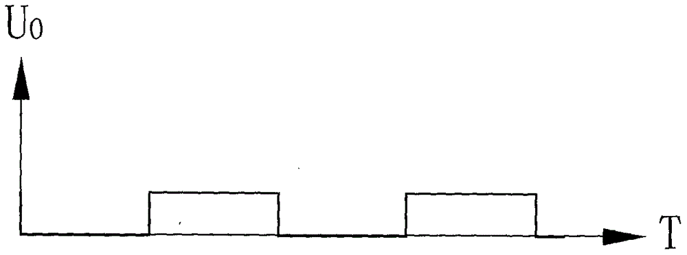
[0022] (1) if figure 2 As shown, the one-way optocoupler zero-point detection module carries out zero-crossing detection to the voltage stabilizer input voltage in real time, and the one-way optocoupler zero-point detection module detects the voltage stabilizer input voltage signal L-in (waveform diagram such as Figure 4 shown) for optocoupler isolation processing,...


PUM


Abstract

The invention relates to the technology of alternating current voltage stabilizers, in particular to a self-adaptive fire-arc-removing relay control method applied to voltage stabilizers. The control method comprises the steps that input voltage and output voltage are subjected to zero-cross detection in real time, timing is carried out on the off action time of all relays, and delaying, regulation and control are carried out on output signals of a relay control module. The self-adaptive fire-arc-removing relay control method aims at being capable of accurately capturing an alternating current zero moment, accurately calculating the on time of different relays and making contacts of different relays exactly at the alternating current zero-cross moment at the off moment in the working process. Compared with the prior art, the input and output voltage zero positions can be more accurately judged; the fire arc phenomenon generated by closing of the relays in the on-load voltage stabilizing process of alternating current voltage stabilizers is eliminated, the control effect of relays is improved, the voltage stabilizing precision is improved, and the service life of voltage stabilizers is prolonged.

Description

technical field [0001] The invention relates to the technology of an AC voltage stabilizer, in particular to a self-adaptive control method for an arc-destroying relay applied to a voltage stabilizer. Background technique [0002] At present, the known non-contact regulated power supply includes a multi-tap transformer, a relay control module, a relay group and a regulated power supply main control module. The AC input voltage is generally between 90V-280V, and the regulated output voltage is 220V±10%V , the AC input voltage range is wide, so in the process of voltage stabilization, the relay control module should switch the relay group in time according to the change of the input and output voltage ratio, and select different input taps and output taps of the transformer, so that the coil turns ratio of the transformer conforms to the input The output voltage ratio changes to ensure that the power regulator can work normally. However, the switching of the relay is carried ...

Claims


Application Information

Patent Timeline
Patent Type & Authority Applications(China)
IPC IPC(8): G05F1/565
CPCG05F1/565
Inventor 滕敏亮滕军腾腾江先志王耀华
Owner ZHEJIANG TTN ELECTRIC
Learn More