
A Micro Bladder Accumulator for Shock Absorber

A technology of shock absorbers and accumulators, applied in the direction of shock absorbers, springs/shock absorbers, shock absorbers, etc., can solve the failure of oil chamber and air chamber isolation seal, frequent movement of floating pistons, and reduced shock absorption effect of automobiles and other problems, to achieve the effect of excellent heat insulation, easy installation, and difficult effect

Inactive Publication Date: 2017-12-22
JIANGSU UNIV
View PDF7 Cites 0 Cited by
  • Summary
  • Abstract
  • Description
  • Claims
  • Application Information

AI Technical Summary

Problems solved by technology

However, there are still many defects in this shock absorber
If the inflation process is too complicated; the damage to the compensation air chamber is not easy or repairable; affected by the road conditions, the floating piston moves frequently, and long-term wear and tear will easily lead to failure of the isolation seal between the oil chamber and the air chamber: the oil in the rodless chamber of the working cylinder is leaked and mixed with compensation gas The gas in the compensation air chamber can easily enter the working cylinder to form bubbles, and the shock absorption effect of the car is significantly reduced at this time; the upper and lower end faces of the floating piston are directly impacted by high-pressure gas and oil in each chamber, and the service life is low

Method used


Image

  • A Micro Bladder Accumulator for Shock Absorber
  • A Micro Bladder Accumulator for Shock Absorber

Examples


Embodiment Construction

[0024] For further elaborating the present invention, now in conjunction with accompanying drawing, the present invention is further described:

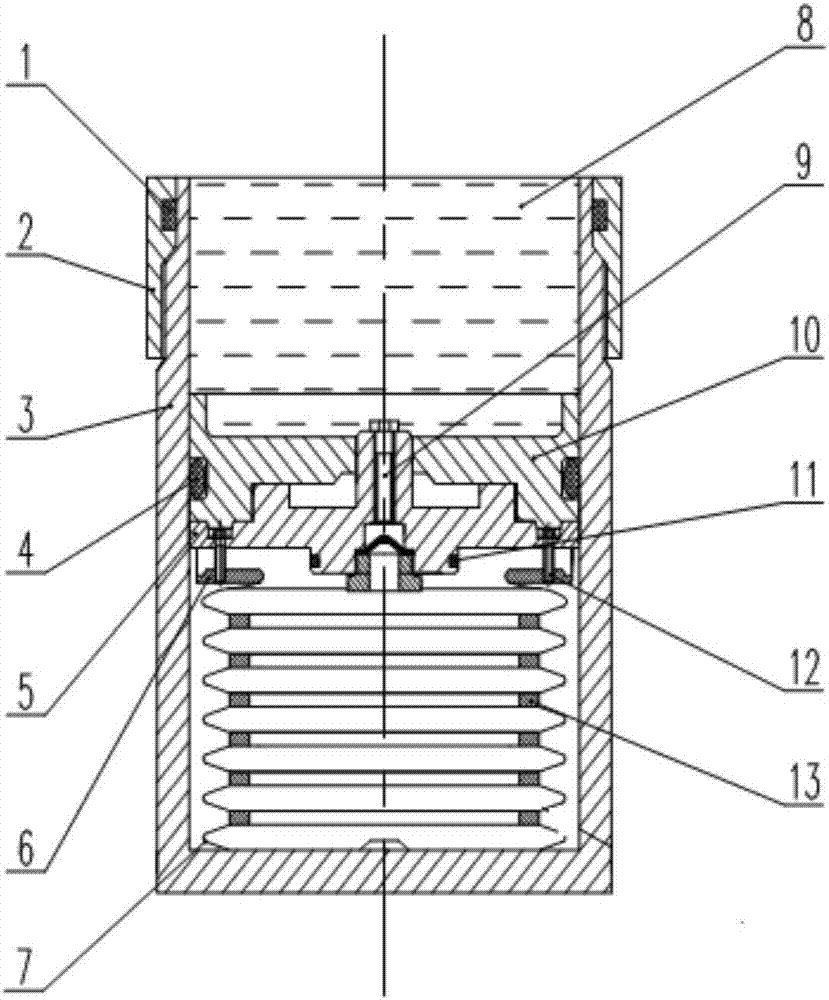
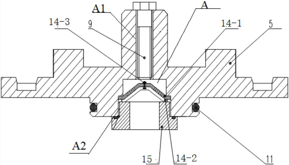
[0025] combined with figure 1 , the outer cylinder 2 and the inner cylinder 3 are connected by threads, wherein an annular groove C is opened on the inner ring of the outer cylinder 2, and an O-ring A1 is installed in the annular groove C, so that the outer cylinder 2 and the inner The sealing of the cylinder 3 ensures that the shock absorbing oil 8 will not leak on the contact side of the outer cylinder 2 and the inner cylinder 3; in addition, the upper end of the junction of the outer cylinder 2 and the inner cylinder 3 is engaged; the inner cylinder 3 Among them, the bladder 7, the air-filled sealing flange 5, the floating piston 10, and the shock absorbing oil 8 on the floating piston 10 are arranged in sequence from bottom to top, wherein the bladder 7 has a folded structure, and is composed of a plurality of flat curved bladder...


PUM


Abstract

The invention discloses a minitype rubber bag accumulator for a shock absorber. A cylinder barrel of a shock absorber compensation chamber is formed by connecting an inner cylinder barrel body and an outer cylinder barrel body into a whole through threads. A gas sealing screw plug is screwed tightly on an inflating sealing flange and arranged in a compensation cavity of the inner cylinder barrel body. The concave part of the bottom of a minitype rubber bag is radially fixed to a protrusion of the bottom end of the cylinder barrel of the shock absorber. Through a floating piston and a minitype rubber bag accumulator assembly installed under the flowing piston, complete isolation of a damping oil chamber and an inert gas chamber is achieved. Fold-type minitype rubber bag outer lugs are sleeved with fastening aluminum alloy flanges, the rubber bag and the fastening aluminum alloy flanges are connected through bolts and the inflating sealing flange, thus isolation of damping oil liquid and high-pressure gas is achieved completely, and oil-gas mixing is avoided. The defect of damping oil liquid flowing filling hysteresis is further overcome, and the idle stroke hidden danger of the shock absorber is avoided. The minitype rubber bag accumulator is different from a traditional rubber bag accumulator, the rubber bag and the damping oil liquid are isolated completely, aging is not liable to occur, the service life of the rubber bag is prolonged, the work responsivity is high through the fold-type appearance design, and the working load bearing ability and impact resistance are high.

Description

technical field [0001] The present invention relates to an accumulator specially used for the shock absorber, especially a micro bladder accumulator used for the shock absorber. In fact, it is an improved floating piston with a special micro air bag with excellent shock absorption performance. Car barrel hydraulic shock absorbers. Background technique [0002] At present, most of the shock absorbers used in automobiles are mainly hydraulic shock absorbers; automobile shock absorbers are installed between the frame and the axle to reduce the impact and vibration caused by the car running on bumpy roads, and to meet the needs of the occupants. ride comfort requirements. When the piston rod of the shock absorber continues to do telescopic movement in the cylinder, the shock absorber oil in the cylinder will repeatedly enter and leave each working chamber through the gap of the valve plate group and the damping hole on the piston, so as to realize oil flow between the chambers ...

Claims


Application Information

Patent Timeline
Patent Type & Authority Patents(China)
IPC IPC(8): F16F9/06F16F9/08F16F9/096F16F9/34
CPCF16F9/065F16F9/067F16F9/082F16F9/096F16F9/34F16F2222/126
Inventor 王存堂张晋张波徐敏健刘烘托
Owner JIANGSU UNIV
Learn More