
Crankshaft-gear connection structure and connection method thereof

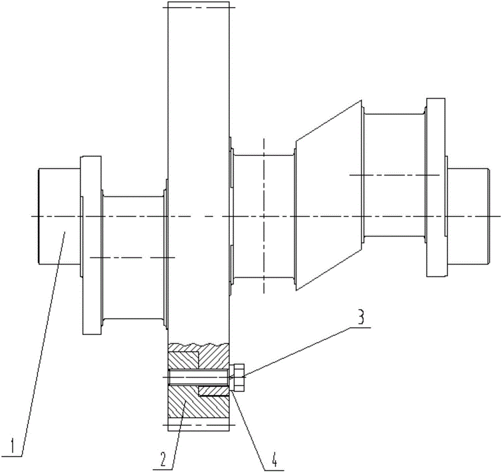
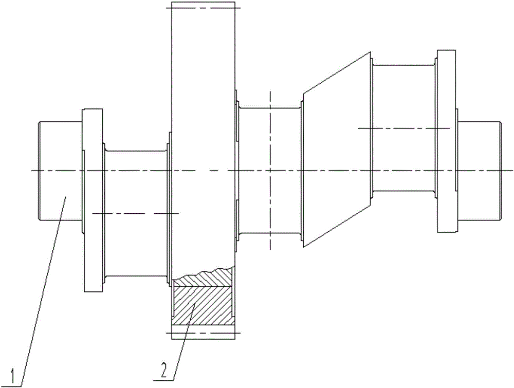
A gear connection and crankshaft technology, applied in the direction of connecting components, shrinkage connections, couplings, etc., can solve the problems of large diameter, broken bolts, large power end volume, etc., to achieve uniform force, small footprint, and torque transmission reliable effect

Pending Publication Date: 2016-11-09
HENGYANG ZHONGDI EQUIP PROSPECTING ENG MACHINERY
View PDF3 Cites 2 Cited by
  • Summary
  • Abstract
  • Description
  • Claims
  • Application Information

AI Technical Summary

Problems solved by technology

The disadvantages of this structure are: 1. Space must be reserved for bolt connection, and the diameter is large, resulting in a large volume of the entire power end; 2. When the mud pump is overloaded, due to uneven force on the bolts, it is easy to cause the bolts fracture

Method used


Image

  • Crankshaft-gear connection structure and connection method thereof
  • Crankshaft-gear connection structure and connection method thereof

Examples


Embodiment 2

[0022] A crankshaft and gear connection method, the steps comprising:

[0023] Step 1: Heating: heat the gear to a temperature of 185-215°C;

[0024] Step 2: heat preservation: heat-preserve the heated gear in step 1, and the heat preservation time is 52-68 minutes;

[0025] Step 3: Installation: install the gear that has been heat-insulated in step 2 on the crankshaft;

[0026] Step 4: Cooling: Cool the assembled crankshaft and gears in air.

[0027] The tolerance fit between crankshaft and gear is H7 / u6.

Embodiment 3

[0029] A crankshaft and gear connection method, the steps comprising:

[0030] Step 1: Heating: heat the gear to a temperature of 190-210°C;

[0031] Step 2: heat preservation: heat-preserve the heated gear in step 1, and the heat preservation time is 55-65 minutes;

[0032] Step 3: Installation: install the gear that has been heat-insulated in step 2 on the crankshaft;

[0033] Step 4: Cooling: Cool the assembled crankshaft and gears in air.

[0034] The tolerance fit between crankshaft and gear is H7 / u6.

Embodiment 4

[0036] A crankshaft and gear connection method, the steps comprising:

[0037] Step 1: Heating: heat the gear to a temperature of 195-205°C;

[0038] Step 2: heat preservation: heat-preserve the heated gear in step 1, and the heat preservation time is 58-62 minutes;

[0039] Step 3: Installation: install the gear that has been heat-insulated in step 2 on the crankshaft;

[0040] Step 4: Cooling: Cool the assembled crankshaft and gears in air.

[0041] The tolerance fit between crankshaft and gear is H7 / u6.


PUM


Abstract

A crankshaft-gear connection structure and a mounting method thereof are provided. The structure includes a crankshaft and a gear. The gear, which is subjected to heating and heat preservation previously, is mounted on the crankshaft in an interference fitting manner. A heating temperature for the gear ranges from 180 to 220 DEG C, and the time of heat preservation ranges from 50 to 70 minutes. The tolerance fit of the crankshaft with the gear is H7 / u6. Due to the use of the above technical solution, the crankshaft-gear connection structure is small in size, reliable in transmitted torque, and stressed uniformly, as compared to the prior art.

Description

technical field [0001] The invention belongs to the field of geological exploration equipment, and in particular relates to a connection structure between a crankshaft and a gear and a connection method thereof. Background technique [0002] In the geological drilling industry, reciprocating mud pumps are essential equipment. With the advancement of technology, mud pumps are also developing towards miniaturization, so as to facilitate airborne matching. In the power end structure of the mud pump, the power is transmitted to the crankshaft through the gear and converts the rotary motion into a reciprocating linear motion. Considering the convenience of processing, the gear and the crankshaft are processed separately and then connected together. [0003] Such as figure 1 As shown, this is the most commonly used crankshaft and gear connection structure on the existing mud pump, including: gear 1, crankshaft 2, bolt 3 and spring washer 4; multiple bolts 3 and spring washers e...

Claims


Application Information

Patent Timeline
IPC IPC(8): F16D1/064F16B4/00
CPCF16B4/006F16D1/064
Inventor 李明星欧阳志强石卫民何秋明
Owner HENGYANG ZHONGDI EQUIP PROSPECTING ENG MACHINERY
Learn More