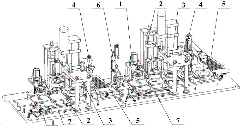
Grease injection and capping machine

A capping machine and grease injection technology, which is applied in the field of bearing processing, can solve the problems of low capping efficiency and high labor intensity, and achieve the effect of realizing automation, improving work efficiency and product qualification rate

Active Publication Date: 2016-11-09
NINGBO ZEE AUTOMATION EQUIP
View PDF6 Cites 14 Cited by
  • Summary
  • Abstract
  • Description
  • Claims
  • Application Information

AI Technical Summary

Problems solved by technology

To solve the technical problems of low efficiency and high labor intensity of manual grease injection and capping existing in the prior art

Method used


Image

  • Grease injection and capping machine
  • Grease injection and capping machine
  • Grease injection and capping machine

Examples


Embodiment Construction

[0048]The technical solutions of the present invention will be clearly and completely described below in conjunction with the accompanying drawings. Apparently, the described embodiments are some of the embodiments of the present invention, but not all of them. Based on the embodiments of the present invention, all other embodiments obtained by persons of ordinary skill in the art without making creative efforts belong to the protection scope of the present invention.

[0049] In the description of the present invention, it should be noted that the terms "center", "upper", "lower", "left", "right", "vertical", "horizontal", "inner", "outer" etc. The indicated orientation or positional relationship is based on the orientation or positional relationship shown in the drawings, and is only for the convenience of describing the present invention and simplifying the description, rather than indicating or implying that the referred device or element must have a specific orientation, o...


PUM


Abstract

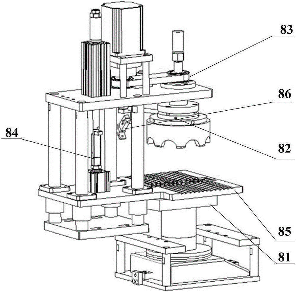
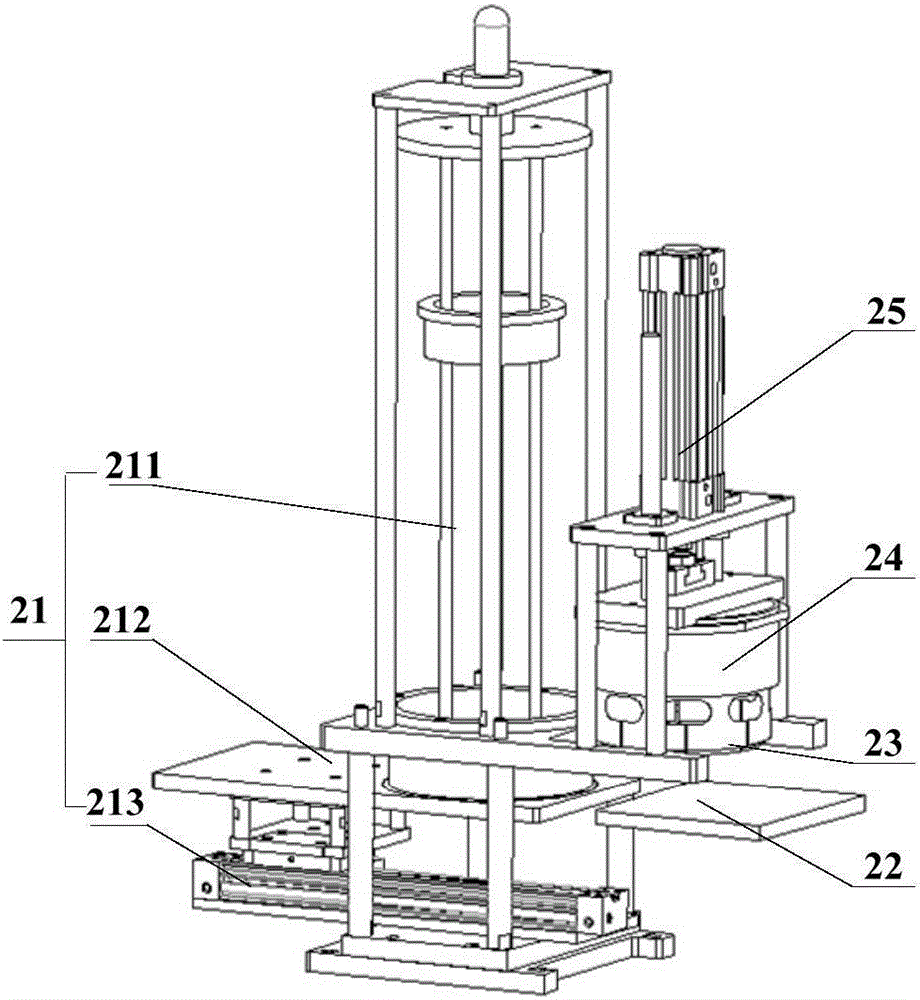
The invention relates to the technical field of bearing machining, in particular to a grease injection and capping machine. The grease injection and capping machine comprises a first operating system, a turning device and a second operating system, wherein the first operating system, the turning device and the second operating device are arranged in sequence. The first operating system and the second operating system each comprise a grease injection weighing device, a sealing cap feeding device, a height detecting device and a rejecting device, wherein the grease injection weighing device, the sealing cap feeding device, the height detecting device and the rejecting device are sequentially arranged in the length direction of a workbench. A conveying device is arranged to convey bearings to be capped to all stations of the first operating system, the turning device and the second operating system. Through the design of the device, grease injection and capping can be achieved, automatic production level of the machine is improved, capping precision and efficiency are improved, the problem of excessively high labor intensity is solved, labor cost investment is reduced, and thus automation development of a company is achieved.

Description

technical field [0001] The invention relates to a bearing processing technology, in particular to a grease injection capping machine. Background technique [0002] A bearing is a precision mechanical element that changes the sliding friction between the running shaft and the shaft seat into rolling friction, thereby reducing friction loss. Its mechanism includes outer ring, inner ring, rolling elements and cage. In addition, in order to reduce the wear between the rolling elements and the inner ring and outer ring during the bearing rotation, during the bearing manufacturing process, grease will be injected between the inner ring and the outer ring. The inner ring and the outer ring are covered to ensure the sealing of the grease and prevent the grease from leaking out. By injecting grease, the friction coefficient of the rolling contact surface can be reduced during the rotation of the bearing, thereby reducing the wear rate between the rolling balls and the inner and out...

Claims


Application Information

Patent Timeline
Patent Type & Authority Applications(China)
IPC IPC(8): F16C43/04
CPCF16C43/04
Inventor 刘建军马盈丰龚洪亮曹景山韩叙霖李伟为
Owner NINGBO ZEE AUTOMATION EQUIP
Why Eureka
Try Eureka