
Battery electric vehicle for the disabled

A technology for electric vehicles and the disabled, which is applied to vehicle parts, elastic suspension, transportation and packaging, etc., and can solve the problems of poor shock absorption and unsuitable driving of electric vehicles

Inactive Publication Date: 2016-11-09
天津中科先进技术产业有限公司
View PDF0 Cites 1 Cited by
  • Summary
  • Abstract
  • Description
  • Claims
  • Application Information

AI Technical Summary

Problems solved by technology

[0004] The purpose of the present invention is to address the technical defects of the prior art and provide an electric vehicle for the disabled to solve the technical problem that the electric vehicle in the prior art is not suitable for driving by the disabled due to poor shock absorption effect

Method used


Image

  • Battery electric vehicle for the disabled

Examples


Embodiment 1

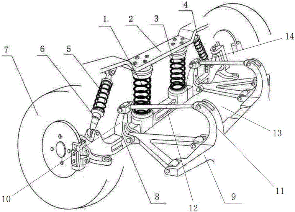
[0020] An electric vehicle for the disabled, the front suspension assembly of the electric vehicle for the disabled includes a first spring 1, a support plate 2, a second spring 3, a third spring 4, a fourth spring 5, and a first hydraulic cylinder 6 , the front wheel 7, the suspension bridge 8, the chassis 9, the first protrusion 10, the second protrusion 11, the connecting rod 12, the pallet 13, the second hydraulic cylinder 14, wherein the front wheel 7 has two, the two are respectively Installed on the two ends of the suspension bridge 8, the lower end of the support plate 2 for supporting the car body is connected with the middle part of the suspension bridge 8 through the first spring 1 and the second spring 3, and one end of the support plate 2 and one end of the suspension bridge 8 pass through the first spring 1 and the second spring 3. The hydraulic cylinder 6 is connected, the other end of the support plate 2 is connected with the other end of the suspension bridge 8...

Embodiment 2

[0027] An electric vehicle for the disabled, the front suspension assembly of the electric vehicle for the disabled includes a first spring 1, a support plate 2, a second spring 3, a third spring 4, a fourth spring 5, and a first hydraulic cylinder 6 , the front wheel 7, the suspension bridge 8, the chassis 9, the first protrusion 10, the second protrusion 11, the connecting rod 12, the pallet 13, the second hydraulic cylinder 14, wherein the front wheel 7 has two, the two are respectively Installed on the two ends of the suspension bridge 8, the lower end of the support plate 2 for supporting the car body is connected with the middle part of the suspension bridge 8 through the first spring 1 and the second spring 3, and one end of the support plate 2 and one end of the suspension bridge 8 pass through the first spring 1 and the second spring 3. The hydraulic cylinder 6 is connected, the other end of the support plate 2 is connected with the other end of the suspension bridge 8...


PUM


Abstract

The invention provides a battery electric vehicle for the disabled. According to the technical scheme, a supporting frame and a suspension axle are connected through two sets of main springs, so that a damping effect is guaranteed in the vertical direction; and meanwhile, in order to solve the problem that a battery electric vehicle low in self-weight generates severe lateral deviation when jolting, oblique hydraulic cylinders are arranged on the edges of the supporting frame and the edges of the suspension axle, and therefore the damping effect is improved. In addition, a horizontal tray is welded between a chassis and the suspension axle, the tray is surrounded by protruding portions and connecting rods, and thus the tray can be used for fixing a battery pack due to the structure. In this mode, the large-weight battery pack is moved forwards to the vehicle head, the self-weight of the vehicle head is increased, and therefore the dragging stability of an engine is improved, and meanwhile vibration and jolting are further relieved. According to the battery electric vehicle, the damping performance of the battery electric vehicle is greatly improved due to the creative design of a front suspension assembly, and the battery electric vehicle is driven more stably and is particularly suitable for the disabled.

Description

technical field [0001] The invention relates to the technical field of electric vehicles, in particular to an electric vehicle for disabled persons. Background technique [0002] An electric vehicle (BEV) refers to a vehicle that is powered by a vehicle-mounted power supply, drives the wheels with a motor, and meets the requirements of road traffic and safety regulations. Due to its smaller impact on the environment than traditional cars, its prospects are widely optimistic, but the current technology is still immature. Pure electric vehicles, compared with fuel vehicles, the main difference (difference) lies in the four major components, drive motor, speed controller, power battery, and on-board charger. Electric vehicles use fuel cells as the power source. The chemical reaction process of the battery will not produce harmful products, so the pollution of electric vehicles is extremely small. Since the energy conversion efficiency of the battery is 2 to 3 times higher than...

Claims


Application Information

Patent Timeline
IPC IPC(8): B60G15/06
CPCB60G15/062B60G15/067
Inventor 吴正斌曹晓燕胡贺宾
Owner 天津中科先进技术产业有限公司
Learn More