hobbing machine hob

A hob and gear hobbing machine technology, which is applied in the direction of gear cutting machines, gear teeth, mechanical equipment, etc., can solve the problems of complex structure and large space occupation, and achieve the effects of reducing labor intensity, simple structure, and reducing space size

Active Publication Date: 2018-01-12
浙江振兴阿祥集团有限公司
View PDF11 Cites 0 Cited by
  • Summary
  • Abstract
  • Description
  • Claims
  • Application Information

AI Technical Summary

Problems solved by technology

In general, the hob tailstock movement guide rail is installed on the hob headstock, and the hob tailstock and hob headstock movement guide rails are connected in parallel, with a complex structure and a large space; the hob tailstock supports the movement of the hob manual hydraulic

Method used


Image

  • hobbing machine hob
  • hobbing machine hob

Examples


Embodiment

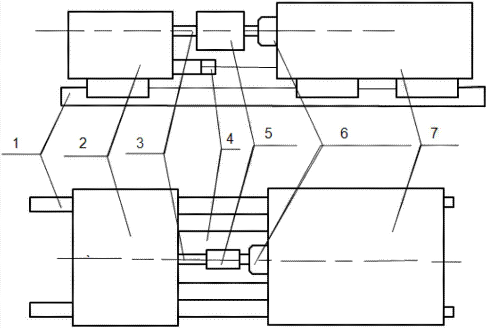
[0023] See figure 2 , the present invention provides a hob frame for a gear hobbing machine, which is composed of a guide rail pair 1, a hob tailstock 2, a tailstock shaft 3, an oil cylinder 4, a hob 5, a hob shaft 6 and a hob headstock 7, wherein,

[0024] The hob tailstock 2 is connected to the hob headstock 7 through the oil cylinder 4;

[0025] The tailstock shaft 3 is mounted on the hob tailstock 2, and the hob shaft 6 is mounted on the hob headstock 7;

[0026] The hob shaft 6 supports or installs one end of the hob 5, and the tailstock shaft 3 supports the other end of the hob 5;

[0027] The oil cylinder 4 provides the axial support force of the tailstock shaft 3 to the hob 5 .

[0028] Further, the hob headstock 7 and the hob tailstock 2 share the same guide rail pair 1 when moving; the hob headstock 7 moves on the guide rail pair 1, and the hob tailstock 2 Moving on the guide rail pair 1, the hob tailstock 2 moves with the hob headstock 7, and the hob tailstock 2...


PUM


Abstract

The invention discloses a hob head of a gear hobbing machine. The hob head consists of a guide rail pair (1), a hob tailstock (2), a tailstock shaft (3), an oil cylinder (4), a hob (5), a hob shaft (6) and a hob spindle box (7), wherein the hob tailstock (2) is connected with the hob spindle box (7) through the oil cylinder (4); the hob spindle box (7) and the hob tailstock (2) share the same guide rail pair (1) during movement; the hob tailstock (2) moves along with the hob spindle box (7); the hob tailstock (2) and the hob spindle box (7) are driven by the oil cylinder (4) to move relative to each other; the oil cylinder (4) provides an axial bearing force of the tailstock shaft (3) to the hob (5).

Description

technical field [0001] The invention relates to the field of gear processing machine tool equipment, in particular to a hob frame for a gear hobbing machine. Background technique [0002] Gear is an important mechanical transmission part, which is widely used in various mechanical equipment. Gear hobbing machine is the most widely used machine tool in gear processing machine tools. Straight teeth, helical teeth and herringbone cylindrical gears can be cut on the gear hobbing machine. Worm gears, sprockets, etc. can also be processed. Existing gear hobbing machines have been widely used in various machinery manufacturing industries such as automobiles, tractors, machine tools, engineering machinery, mining machinery, metallurgical machinery, petroleum, instruments, aircraft and spacecraft. At present, gear hobbing machines generally use spiral hobs to process gears according to the generation method, while gears processed by hobs are generally interrupted cutting. [0003] ...

Claims


Application Information

Patent Timeline
Patent Type & Authority Patents(China)
IPC IPC(8): B23F23/12
CPCB23F23/1243
Inventor 黄伟灵白洪华吴荣建胡超荣吴英姿陶树强
Owner 浙江振兴阿祥集团有限公司
Why Eureka
Try Eureka