Actuating mechanism of mechanical shearing machine

A technology for actuators and shearing machines, which is applied to the attachment of shearing machines, shearing devices, and shearing machine equipment, etc. It can solve the problems that the mounting base is not convenient for fixed installation, and the installation position cannot be adjusted according to actual needs. The effect of easy installation

Active Publication Date: 2019-04-19
郑州辛西亚信息科技有限公司
View PDF4 Cites 0 Cited by
  • Summary
  • Abstract
  • Description
  • Claims
  • Application Information

AI Technical Summary

Problems solved by technology

[0002] The mechanical shearing machine adopts the clutch structure of resistance key and open gear transmission, and adopts more advanced electrical operation, with low noise and convenient operation and maintenance; the mechanical shearing machine adopts all-steel welding structure, which is simple in structure, easy to operate, and beautiful in appearance. The energy consumption is low, and the actuator of the mechanical shearing machine is an important part of the mechanical shearing machine. The actuator of the mechanical shearing machine includes a side bracket and a main shaft rotatably mounted on the side bracket. The left sealing cover, the eccentric wheel and the right sealing cover, the sliding sleeve on the eccentric wheel is provided with a pendulum shell, and the main shaft is also equipped with a mounting seat fixedly installed with the mechanical shearing machine, because the installation position of the mounting seat and the main shaft cannot Adjustments are actually required and the mount is not convenient for fixed mounting on mechanical shears

Method used


Image

  • Actuating mechanism of mechanical shearing machine
  • Actuating mechanism of mechanical shearing machine
  • Actuating mechanism of mechanical shearing machine

Examples


Embodiment

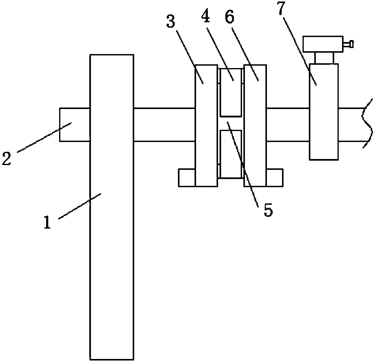
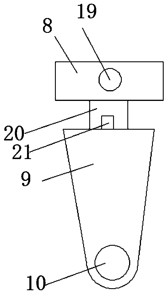
[0029] refer to Figure 1-7, the executive mechanism of the mechanical shearing machine is proposed in this embodiment, including a side bracket 1, a main shaft 2 is mounted on the side bracket 1 for horizontal rotation, the outer key of the main shaft 2 is connected with an eccentric wheel 5, and the outer side of the eccentric wheel 5 is movable The pendulum shell 4 is set, and the side of the pendulum shell 4 close to the side bracket 1 is installed with the left sealing cover 3 fixedly set with the outside of the main shaft 2, and the other side of the pendulum shell 4 is installed with the outside of the main shaft 2. Right sealing cover 6, the side of right sealing cover 6 away from eccentric wheel 5 is provided with adjustable mounting seat 7, and adjustable mounting seat 7 comprises fixed seat 8 and is positioned at the vertical moving seat 9 below fixed seat 8, and moves vertically The seat 9 is provided with a main shaft through hole 10 which is installed in rotation...


PUM


Abstract

The invention discloses an executing mechanism for a mechanical-type plate shearing machine. The executing mechanism comprises a side support; a spindle is horizontally rotatably mounted on the side support, the outer side of the spindle is in key connection with an eccentric wheel, and the outer side of the eccentric wheel is movably sleeved with a swing block shell; the side, close to the side support, of the swing block shell is provided with a left sealing cover fixedly arranged on the outer side of the spindle in a sleeving mode, and the other side of the swing block shell is provided with a right sealing cover fixedly arranged on the outer side of the spindle in a sleeving mode; and the side, away from the eccentric wheel, of the right sealing cover is provided with an adjustable mounting seat which comprises a fixing seat and a vertical moving seat located below the fixing seat, and a spindle through hole which is rotatably formed in the spindle is formed in the vertical movingseat. According to the executing mechanism, the economical and practical effects are achieved, the distance between the vertical moving seat and the fixing seat inside the adjustable mounting seat canbe adjusted according to the actual requirement, and the fixing seat inside the adjustable mounting seat is mounted on the mechanical-type plate shearing machine advantageously through a threaded rod.

Description

technical field [0001] The invention relates to the technical field of mechanical shears, in particular to an actuator of the mechanical shears. Background technique [0002] The mechanical shearing machine adopts the clutch structure of resistance key and open gear transmission, and adopts more advanced electrical appliances to operate, with low noise and convenient operation and maintenance; the mechanical shearing machine adopts all-steel welding structure, which is simple in structure, easy to operate, and beautiful in appearance. The energy consumption is low, and the actuator of the mechanical shearing machine is an important part of the mechanical shearing machine. The actuator of the mechanical shearing machine includes a side bracket and a main shaft rotatably mounted on the side bracket. The left sealing cover, the eccentric wheel and the right sealing cover, the sliding sleeve on the eccentric wheel is provided with a pendulum shell, and the main shaft is also equ...

Claims


Application Information

Patent Timeline
Patent Type & Authority Patents(China)
IPC IPC(8): B23D33/00B23D15/06
CPCB23D15/06B23D33/00
Inventor 郭文英
Owner 郑州辛西亚信息科技有限公司
Why Eureka
Try Eureka