
Spiral cooling machine room

A spiral cooling and cooling room technology, applied in cooling/ventilation/heating renovation, electrical components, electrical equipment structural parts, etc., can solve the problems of high cooling cost, reduced cooling effect, loud noise, etc.

Active Publication Date: 2018-05-01
江苏惠沣环保科技有限公司
View PDF10 Cites 0 Cited by
  • Summary
  • Abstract
  • Description
  • Claims
  • Application Information

AI Technical Summary

Problems solved by technology

[0002] With the rapid development of the Internet industry, the scale of data centers continues to expand; in today's ever-changing world, stable infrastructure construction serves as the cornerstone for Internet companies to continue to grow to a certain extent, and enterprise data centers have gradually become the confidential core of enterprises One; each server in the computer room in the data center continues to run at high speed to ensure the exchange, calculation and operation of enterprise data; because the computer room will continue to generate a large amount of heat, when testing the working status of the computer room, the computer room The cooling effect has become one of the important considerations; the traditional computer room only uses air conditioners to cool down, and the long-term use of the air conditioner will generate a lot of noise. At the same time, the cooling effect will decrease with the aging of the machine, and the cooling cost is high

Method used


Image

  • Spiral cooling machine room
  • Spiral cooling machine room

Examples


Embodiment

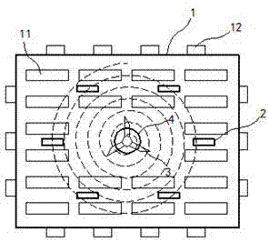
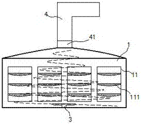
[0016] exist figure 1 , figure 2 In the shown embodiment, the spiral cooling machine room includes a cooling room 1, and brackets 11 are arranged in an array in the cooling room 1,

[0017] Each bracket 11 is equidistantly fixed with a support plate 111 from top to bottom; the lower edge of the section of the support plate 111 is a streamlined downward convex; the server is detachably placed on each support plate 111; There are air inlet windows 12 on the four walls, and purification nets are installed on the windows of each air inlet window 12; with the geometric center of the floor of the cooling room 1 as a dot, six circulating fans 2 are arranged in a rotationally symmetrical manner, and each The air inlet pipe and the air outlet pipe of the circulating fan 2 are rotationally symmetrical; each of the circulating fans 2 is powered by an independent circuit; a guide fan 3 is installed on the geometric center of the floor of the cooling room 1, and the air outlet surface of...


PUM


Abstract

The invention relates to a spiral cooling machine room. The spiral cooling machine room comprises a cooling room; brackets are arranged in an array form in the cooling room; supporting plates are fixedly arranged at an equal interval on each bracket from top to bottom; a server is arranged in a detachable manner on each supporting plate; four walls of the cooling room are provided with air inlet windows; a purification net is mounted at a window opening of each air inlet window; by using the geometric center of the floor of the cooling room as the dot, circulating fans are rotationally and symmetrically arranged, and an air inlet pipe and an air outlet pipe of each circulating fan are rotationally symmetric; each circulating fan is supplied with power by adopting an independent circuit; a top plate of the cooling room is an upwards convex arc surface, an air suction pipe is mounted at the center of the top plate, and the air suction pipe extends upwards and extends out of the wall; and the machine room is simple in structure and excellent in air ventilation, the temperature of the machine room can be controlled under low cost, and a suitable working temperature is risen for the servers.

Description

technical field [0001] The invention relates to a large-scale facility in the computer field, in particular to a computer room. Background technique [0002] With the rapid development of the Internet industry, the scale of data centers continues to expand; in today's ever-changing world, stable infrastructure construction serves as the cornerstone for Internet companies to continue to grow to a certain extent, and enterprise data centers have gradually become the confidential core of enterprises One; each server in the computer room in the data center continues to run at high speed to ensure the exchange, calculation and operation of enterprise data; because the computer room will continue to generate a large amount of heat, when testing the working status of the computer room, the computer room The cooling effect has become one of the important considerations. Traditional computer rooms only use air conditioners to cool down. Long-term use of the air conditioner will gener...

Claims


Application Information

Patent Timeline
Patent Type & Authority Patents(China)
IPC IPC(8): H05K7/20
CPCH05K7/20745
Inventor 仲杏英
Owner 江苏惠沣环保科技有限公司
Learn More