Rotor structure of a built-in permanent magnet synchronous motor

A permanent magnet synchronous motor and rotor structure technology, applied in synchronous machine parts, magnetic circuit shape/style/structure, magnetic circuit rotating parts, etc. times, achieve mutual cancellation, and improve power and torque density.

Active Publication Date: 2019-02-19
广州爱知电机有限公司
View PDF4 Cites 0 Cited by
  • Summary
  • Abstract
  • Description
  • Claims
  • Application Information

AI Technical Summary

Problems solved by technology

At present, in the cost of permanent magnet motors, permanent magnet materials occupy a large proportion, which causes the competitiveness of permanent magnet motors in low-end applications to decline

Method used


Image

  • Rotor structure of a built-in permanent magnet synchronous motor
  • Rotor structure of a built-in permanent magnet synchronous motor
  • Rotor structure of a built-in permanent magnet synchronous motor

Examples


Embodiment 1

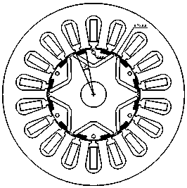
[0024] Such as figure 2 As shown, this embodiment has a structure of 6 poles and 18 slots, adopts a distributed winding structure, and the angle of the center of the rotor occupied by the arc-shaped slots on the outer layer is 14°. The diameter of the circular hole 4 is 2mm, and the radius of the semicircular groove on the outer edge of the rotor core is 0.75mm.

Embodiment 2

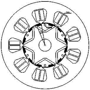
[0026] Such as image 3 As shown, this embodiment has a structure of 6 poles and 9 slots, adopts a centralized winding structure, and the angle of the center of the rotor occupied by the arc-shaped slots on the outer layer is 18°. The diameter of the circular hole 4 is 2.5mm, and the radius of the semicircular groove on the outer edge of the rotor core is 1mm.

Embodiment 3

[0028] Such as Figure 4 As shown, this embodiment has a structure of 8 poles and 12 slots, adopts a centralized winding structure, and the angle of the center of the rotor occupied by the outer arc-shaped slots is 10°. The diameter of the circular hole 4 is 2mm, and the radius of the semicircular groove on the outer edge of the rotor core is 1.5mm.


PUM


Abstract

The invention discloses a rotor structure of a built-in permanent magnet synchronous motor. A rotor iron core is formed by laminating silicon steel sheets. V-shaped permanent magnet slots which face towards the outer ring of a rotor and are used for embedding permanent magnets are arranged on the rotor iron core. A shaft axis is formed between the midpoint of each V-shaped permanent magnet slot and the circle center of the rotor. Each V-shaped permanent magnet slot is symmetrical left and right in relation to the shaft axis. An inner arched slot and an outer arched slot with aligned tail ends are arranged at the left top end and the right top end of each V-shaped permanent magnet slot along the outer peripheral direction of the rotor. A round hole slot is arranged in each V-shaped permanent magnet slot close to the outer periphery of the rotor. The circle center of the round hole slot is arranged on the shaft axis. A semicircular slot is arranged on the outer edge of the rotor iron core. The semicircular slot is arranged between two adjacent V-shaped permanent magnet slots. According to the rotor structure, permanent magnet torque and reluctance torque are configured reasonably, the utilization rate of the permanent magnets is improved, the power density and efficiency of the motor are improved, and the cogging torque is reduced.

Description

technical field [0001] The invention relates to a rotor structure of a permanent magnet synchronous motor, in particular to a rotor structure of a built-in permanent magnet synchronous motor, which is suitable for application fields such as air conditioners, compressors and electric tools, and belongs to the technical field of motors. Background technique [0002] Permanent magnet motors have the characteristics of high power density, high efficiency, and high reliability, and have been widely used in industrial production and household life. At present, in the cost of permanent magnet motors, permanent magnet materials occupy a large proportion, which causes the competitiveness of permanent magnet motors in low-end applications to decline. In order to improve the utilization rate of permanent magnets and the price competitiveness of permanent magnet motors, optimizing the structure of permanent magnet motors to improve their power and torque density has become an important ...

Claims


Application Information

Patent Timeline
Patent Type & Authority Patents(China)
IPC IPC(8): H02K1/27H02K21/02
CPCH02K1/27H02K21/02
Inventor 林明耀单爱进徐磊王琪蒋建宏
Owner 广州爱知电机有限公司
Why Eureka
Try Eureka