
Ultrasonic fatigue testing method of cylindrical sample with uniform cross sections

A fatigue test, cylindrical technology, used in the analysis of solids, instruments, and materials using sonic/ultrasonic/infrasonic waves, which can solve the problems of unstable test, difficult to complete mechanical processing, deviation between actual vibration displacement value and theoretical value, etc. Achieve the effect of saving test cost, accelerating fatigue test, and small processing error

Inactive Publication Date: 2016-10-26
武汉钢铁有限公司
View PDF2 Cites 6 Cited by
  • Summary
  • Abstract
  • Description
  • Claims
  • Application Information

AI Technical Summary

Problems solved by technology

[0006] 1) When designing cylindrical and other ultrasonic fatigue samples with transition arcs, in order to facilitate analytical calculations, it is generally assumed that the curve of the variable section section of the sample is a catenary line, but it is difficult to complete mechanical processing. Usually, in actual processing, a circle is used The arc surface is used to replace the catenary surface. This substitution will cause the actual vibration displacement value of the sample to deviate from the theoretical value, thus affecting the accuracy of the ultrasonic fatigue test results.
[0007] 2) The fatigue test has higher requirements on the surface finish of the sample, especially the ultra-high cycle fatigue test has higher requirements on the surface finish of the sample. The cylindrical sample with a transition arc makes it more difficult to polish the sample due to the transition arc in the middle, so that Affects the surface finish of the specimen
For some materials with a low strength level, if the test is designed as a cylindrical specimen with a transition arc, the displacement amplitude may be too small to cause the test to be unstable or even unable to vibrate

Method used


Image

  • Ultrasonic fatigue testing method of cylindrical sample with uniform cross sections
  • Ultrasonic fatigue testing method of cylindrical sample with uniform cross sections
  • Ultrasonic fatigue testing method of cylindrical sample with uniform cross sections

Examples


Embodiment Construction

[0050] The present invention will be further described in detail below in conjunction with the accompanying drawings and specific embodiments.

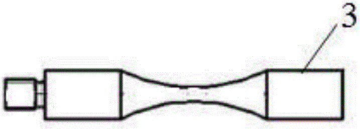
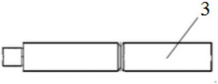
[0051] Such as Figure 1~2 Shown is a schematic diagram of the structure of the cylindrical specimen with transition arc and the cylindrical specimen with notch used in the conventional ultrasonic fatigue test method.

[0052] Such as Figure 5As shown, it is the USF-2000 ultrasonic fatigue testing machine produced by Shimadzu Corporation of Japan, and its resonance frequency is 20KHz. The ultrasonic fatigue testing machine is mainly composed of a transducer 1 , a displacement amplifier 2 , a cooling air nozzle 4 , an ultrasonic generator 5 and a system control software 6 . Wherein, the ultrasonic generator 5 converts the electrical signal of 50 Hz into an ultrasonic sine wave electrical signal of 20 KHz, and changes the amplitude of the sine wave by adjusting the voltage; the transducer 1 converts the electrical signal provided by ...


PUM


Abstract

The invention discloses an ultrasonic fatigue testing method of a cylindrical sample with uniform cross sections. The method comprises the following steps: (1) determining the size of a cylindrical sample with uniform cross sections; (2) processing a material into a cylindrical sample with uniform cross sections; (3) fixing the cylindrical sample in a displacement amplifier of an ultrasonic fatigue testing machine; (4) starting ultrasonic fatigue system control software, picking the sample type as a transition arc containing cylindrical sample, and determining the size of the transition arc containing cylindrical sample; (5) determining the stress amplitude ([sigma]<max>) that is loaded on the cylindrical sample, and calculating the stress amplitude ([sigma]<0><max>) that is loaded on the transition arc containing cylindrical sample under a same displacement amplitude; (6) inputting the stress amplitude ([sigma]<0><max>) into the ultrasonic fatigue system control software, setting other test parameters, and starting an ultrasonic fatigue test until the sample is broken down. The ultrasonic fatigue test control of a cylindrical sample with uniform cross sections is indirectly realized through the ultrasonic fatigue test control of a transition arc containing cylindrical sample.

Description

technical field [0001] The invention relates to an ultrasonic fatigue test method for metal materials, in particular to an ultrasonic fatigue test method for cylindrical samples with equal cross-sections. Background technique [0002] Ultrasonic fatigue test is a new technology for testing the fatigue performance of materials. It uses piezoelectric ceramic transducers to convert electrical signals supplied by high-frequency power supplies into mechanical vibrations of the same frequency, which are then amplified by vibration displacement amplifiers. One end of the sample is connected to the displacement amplifier, and the other end is free. Resonance occurs under the excitation of the displacement amplifier, and a resonant wave is generated in the sample, forming a tension-compression symmetric cyclic load along the axial direction of the sample, and establishing a longitudinal displacement and stress (strain) field. [0003] Compared with the traditional fatigue testing te...

Claims


Application Information

Patent Timeline
IPC IPC(8): G01N29/12
CPCG01N29/12G01N2291/0234G01N2291/262
Inventor 彭文杰骆海贺严龙薛欢刘冬邝兰翔
Owner 武汉钢铁有限公司
Learn More