Cylinder head assembly

A cylinder head and component technology, applied in the field of component temperature, can solve the problems of small temperature measurement range, uncertainty of operating temperature, and high technical complexity of temperature measurement

Inactive Publication Date: 2016-10-26
DR ING H C F PORSCHE AG
View PDF9 Cites 5 Cited by
  • Summary
  • Abstract
  • Description
  • Claims
  • Application Information

AI Technical Summary

Problems solved by technology

[0008] Disadvantages of the known methods are the small temperature measurement range, the low measurement accuracy and the high technical complexity involved in measuring the temperature, wherein in some cases, however, the temperature measurement cannot be carried out under actual conditions, and consequently the measured operating Uncertainty about temperature

Method used


Image

  • Cylinder head assembly
  • Cylinder head assembly
  • Cylinder head assembly

Examples


Embodiment Construction

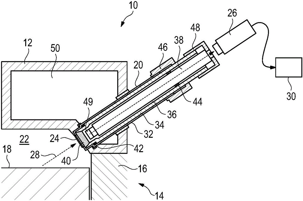
[0042] figure 1 A schematic partial view of the cylinder head assembly is shown, generally designated 10 . The cylinder head assembly 10 generally has a housing 12 that defines the cylinder head assembly 10 on the outside. The cylinder head assembly 10 is connected to the figure 1 The engine block 14 , which is only schematically shown in a partial view in , has at least one cylinder 16 in which at least one piston 18 is accommodated. As a result of the high power densities of modern internal combustion engines, the thermal load, especially of the piston 18, is very high, with the result that the actual operating temperature of the piston and its surfaces has to be measured frequently during the development phase in order to avoid the operation of the final product During excessive heat load.

[0043] exist figure 1 The cylinder head assembly also has optical passages 20 formed in the housing 12 and having openings 24 assigned to the combustion chambers 22 of the engine bl...


PUM


Abstract

A cylinder head (10) for an internal combustion engine has a housing (12) that is assigned a multiplicity of elements (18). An optical channel (20) is formed in the housing (12) and is assigned to at least one of the elements (18). The optical channel (20) is assigned a thermography camera (26) that is designed to detect infrared radiation (28) from the at least one element (28) through the optical channel (20) to make available a thermography image (52) of the at least one element (18).

Description

technical field [0001] The invention relates to a cylinder head assembly for an internal combustion engine, which has a housing and an optical channel to which elements are assigned, the optical channel being formed in the housing and being assigned to at least one of these elements. [0002] The invention also relates to a method for measuring the temperature of an element of an internal combustion engine. [0003] The invention finally relates to an internal combustion engine for a motor vehicle, which has an engine block with at least a cylinder and a piston. Background technique [0004] In the field of motor vehicle technology, legal requirements and customer requirements have led to low-consumption internal combustion engines with ever-increasing rated engine powers. This increased power density results in an increase in thermal energy that is expelled from the combustion chamber as waste heat into the cooling system and the surrounding environment. As a result of t...

Claims


Application Information

Patent Timeline
Patent Type & Authority Applications(China)
IPC IPC(8): G01J5/00F02F1/24
CPCF02F1/24G01J5/0022H04N23/55G02B7/028G02B23/2446G02B23/2492G01J5/0818G01J2005/0077G02B13/0095G02B13/14H04N5/33H04N23/57G01J3/0248G01J3/108G01J5/60G01K13/04G02B6/0015G02B6/0063G01J5/48H04N23/51G01J5/08G02B7/008
Inventor M·菲舍尔
Owner DR ING H C F PORSCHE AG
Why Eureka
Try Eureka