
Interference imaging spectrometer and interferometer

A technology of interference imaging and interferometer, which is applied in the fields of interference spectroscopy, instruments, spectrum investigation, etc., can solve problems such as difficult constraints, processing and assembly technology, complex structure of interferometer, etc., and achieve high energy utilization rate and realize The effect of sub-pixel super-resolution detection, convenient configuration and expansion

Inactive Publication Date: 2016-10-26
XI'AN INST OF OPTICS & FINE MECHANICS - CHINESE ACAD OF SCI
View PDF5 Cites 4 Cited by
  • Summary
  • Abstract
  • Description
  • Claims
  • Application Information

AI Technical Summary

Problems solved by technology

The Mach-Zehnder interferometer has a completely separated dual optical path spectroscopic type, with the characteristics of dual-port input and output, which can easily configure the detection requirements of the imaging optical path, such as the full-field full-aperture calibration can be directly realized in the optical path without additional auxiliary The optical path can be extended by dual detectors or sub-pixel technology can be used to achieve super-resolution imaging. However, due to the complex structure of the interferometer itself and the difficulty in processing and assembly technology, the application is restricted.

Method used


Image

  • Interference imaging spectrometer and interferometer
  • Interference imaging spectrometer and interferometer
  • Interference imaging spectrometer and interferometer

Examples


Embodiment Construction

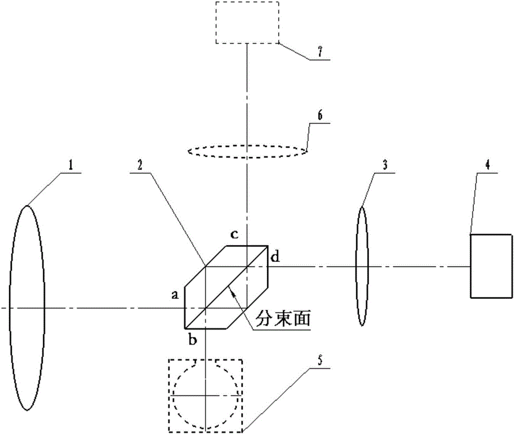
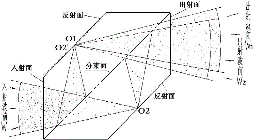
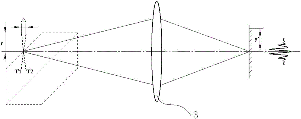
[0039] Such as figure 1 As shown, the interferometer has four end faces a, b, c, and d, which can be set as two incident end faces and two outgoing end faces respectively. The front imaging objective lens 1 collects the energy from the target scene and forms an image on the primary image plane. The isosceles trapezoidal prism interferometer 2 is placed at the position of the primary image plane (that is, the focal plane position of the front imaging objective lens), the imaging light of the target scene is incident on the incident end a of the interferometer, and is divided into The two beams respectively pass through the reflective surface of the interferometer and then merge through the beam splitting surface. The combined two beams of light generate transverse shear and interfere at the position of the primary image plane. The imaging coupling mirror 3 is imaged on the photodetector 4 for reception.

[0040] The first part 5 of the incident light path of the incident end b...


PUM

PropertyMeasurementUnit
Bottom corneraaaaaaaaaa

Abstract

The invention discloses an interference imaging spectrometer and an interferometer. The interference imaging spectrometer includes a preposed imaging object lens, the interferometer, an imaging coupling mirror, and a photoelectric detector, the interferometer includes two same isosceles trapezoid prisms, the lower bottom surfaces of the two isosceles trapezoids are glued, the glued surfaces are beam splitting surfaces, the upper bottom surfaces of the two isosceles trapezoids are reflection planes, two adjacent waist surfaces of the four waist surfaces of the two isosceles trapezoid prisms are two incent ends of the interferometer, and the other two waist surfaces are two emitting ends of the interferometer. The interference imaging spectrometer is high in sensitivity and compact in structure, easy to realize a high spatial resolution light path, and easy to realize wide coverage imaging, dual-port incident and emitting surfaces can realize full-field-view and full-aperture calibration without the need for an additional auxiliary optical path, and the expansion of the spectrum band can be realized by the reception of dual detectors and the super-resolution imaging can be realized by sub-pixel technology, and the interferometer prisms have the advantages of easy processing and assembling.

Description

technical field [0001] The invention relates to an interference spectrum imaging technology, that is, a Fourier transform spectrum imaging technology, in particular to an interference imaging spectrometer and an interferometer. Background technique [0002] Interference spectral imaging technology can be divided into two types: pupil plane interference and image plane interference in principle. The typical technology of pupil plane interference is spatial modulation interference spectrum imaging technology, which is characterized in that the spectrum of the measured target can be obtained by an interferogram , its spectral information is not affected by the attitude of the carrying platform. This optical path principle is to expand and collimate the energy from the target scene element to the pupil plane, thus limiting its sensitivity. [0003] The technical principle of image plane interference can be divided into equal-tilt interference imaging based on parallel optical pa...

Claims


Application Information

Patent Timeline
IPC IPC(8): G01J3/45G01B9/02
CPCG01B9/02017G01B9/02044G01J3/45
Inventor 白清兰李立波冯玉涛邹纯博孙剑刘欢李芸闫鹏胡炳墚
Owner XI'AN INST OF OPTICS & FINE MECHANICS - CHINESE ACAD OF SCI
Learn More