A desulfurization pump lined with resin silicon carbide

A technology of silicon carbide and desulfurization pumps, which is applied to parts, pumps, and pump components of pumping devices for elastic fluids, and can solve problems such as cracks, complex impeller shapes, and resin silicon carbide lining cracks, etc., to reduce The effect of craft difficulty

Active Publication Date: 2019-05-03
HUBEI TOMAS FLUID TECH CO LTD +1
View PDF10 Cites 0 Cited by
  • Summary
  • Abstract
  • Description
  • Claims
  • Application Information

AI Technical Summary

Problems solved by technology

1. Due to the limitations of the strength and toughness of the resin silicon carbide in the prior art, the prior art can only produce small-sized resin-lined silicon carbide centrifugal pumps, but the preparation of large-flow, large-lift resin-lined silicon carbide 2. As one of the important flow parts, the impeller needs to bear the impact of torque and conveying medium at the same time. Therefore, it is necessary to set up an impeller with a metal skeleton and a resin silicon carbide lining. However, due to The shape of the impeller is complex, and the resin silicon carbide lining is not easy to manufacture. Moreover, the resin silicon carbide lining and the impeller frame are not firmly bonded. During the operation of the impeller, the resin silicon carbide lining is prone to micro-cracks, and even falls off in severe cases.
3. The thermal expansion coefficients of the resin silicon carbide lining and the metal pump casing are different, and the pump body is subjected to temperature, pressure and vibration during use, which makes the resin silicon carbide lining in the pump body easy to expand and crack. The combination of the metal pump casing is not firm, and it is prone to cracks and even breaks during use

Method used


Image

  • A desulfurization pump lined with resin silicon carbide
  • A desulfurization pump lined with resin silicon carbide
  • A desulfurization pump lined with resin silicon carbide

Examples


Embodiment Construction

[0095] The technical scheme of the inventive resin-lined silicon carbide desulfurization pump and its preparation method will be further described below in conjunction with the accompanying drawings, so that those skilled in the art can better understand the present invention and implement it.

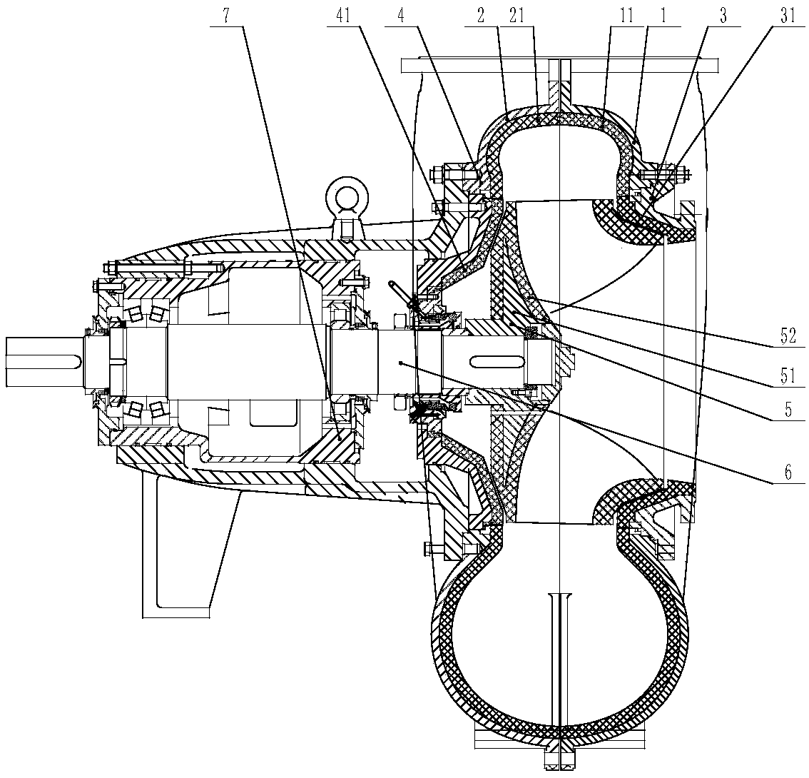
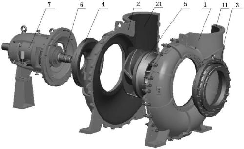
[0096] see figure 1 , the present invention provides a resin-lined silicon carbide desulfurization pump, comprising a pump body, a front pump cover 3 and a rear pump cover 4 arranged at both ends of the pump body, a pump shaft 6 passes through the rear pump cover 4 and extends into the pump body, and the end The impeller 5 is arranged, and the impeller 5 is axially fixed by the impeller bolts. The radial direction of the impeller 5 and the pump shaft 6 is fixed by a key connection. The other end of the pump shaft 6 is provided with a bearing assembly 7 and connected with the motor. In the desulfurization pump lined with resin silicon carbide of the present invention, the pump body is c...


PUM

PropertyMeasurementUnit
pore sizeaaaaaaaaaa
densityaaaaaaaaaa
densityaaaaaaaaaa

Abstract

The invention provides a desulphurization pump with resin silicon carbide linings and a preparing method of the desulphurization pump. A pump body is formed by fixing a front pump shell and a rear pump shell in a covering manner. The front pump shell lining and the rear pump shell lining are arranged on the inner wall of the front pump shell and the inner wall of the rear pump shell correspondingly; the front pump cover lining and the rear pump cover lining are arranged on a front pump cover and a rear pump cover correspondingly; an impeller is formed by arranging the impeller lining outside an integral metal impeller framework; and all the above lining bodies are made of resin silicon carbide materials. The preparing method of the desulphurization pump includes the steps that the front pump shell lining and the rear pump shell lining are formed on the inner wall of the front pump shell and the inner wall of the rear pump shell correspondingly; then the front pump shell and the rear pump shell are combined in a covering manner and are fixed through bolts; and implementation is easy. By means of the desulphurization pump with the resin silicon carbide linings, the flow ranges from 800 m<3> / h to 18,000 m<3> / h, the lift ranges from 15 m to 44 m, the rotating speed ranges from 495 r / min to 1,450 r / min, the pump is suitable for conveying of media of which the pH value ranges from 2.5 to 13, the chloride ion concentration is smaller than or equal to 60,000 ppm, the weight concentration is smaller than or equal to 60% and the temperature is smaller than or equal to 100 DEG C, and the pump is particularly suitable for a limestone / gypsum wet flue gas desulphurization technology.

Description

technical field [0001] The invention relates to a desulfurization pump and a preparation method thereof, in particular to a resin-lined silicon carbide desulfurization pump and a preparation method thereof, belonging to the technical field of fluid equipment. Background technique [0002] The desulfurization pump is a centrifugal pump in terms of working principle. It is used in the wet desulfurization industry as a slurry circulation pump to transport limestone slurry or gypsum slurry. In the process of use, the acid-base of the conveying medium alternates, which severely corrodes the flow parts of the desulfurization pump. At the same time, the conveying medium has a high concentration of chloride ions, which further aggravates the corrosion of the flow parts. At the same time, the conveying medium contains high concentration, Solid particles with high density will cause abrasion to the flow parts, therefore, high requirements are put forward for the corrosion resistance a...

Claims


Application Information

Patent Timeline
Patent Type & Authority Patents(China)
IPC IPC(8): F04D29/02F04D29/42F04D29/22B28B1/14B28B7/00C04B26/14C04B14/32C04B111/23C04B111/20
CPCB28B1/14B28B7/0011B28B7/0014B28B7/0029C04B26/14C04B2111/2038C04B2111/23F04D29/026F04D29/2294F04D29/4286F05D2300/2261C04B14/324C04B20/0076C04B2103/0068C04B24/42
Inventor 陈敬李宗来余小峰李再勇阳白梅
Owner HUBEI TOMAS FLUID TECH CO LTD
Why Eureka
Try Eureka