
Gear tooth groove finishing device

A gear and tooth groove technology, applied in the field of gear finishing, can solve the problems of increasing the wear intensity of gears, shortening the service life of gears, and affecting the smoothness of gears, etc., so as to reduce workload, improve processing efficiency and fast processing speed Effect

Active Publication Date: 2018-10-09
重庆市綦江区余诚齿轮有限公司
View PDF6 Cites 1 Cited by
  • Summary
  • Abstract
  • Description
  • Claims
  • Application Information

AI Technical Summary

Problems solved by technology

[0002] During the production process of gears, the tooth grooves on the gears will leave some scratches or cuts in the tooth grooves after the gear shaping machine cuts the grooves, which makes the inner side of the tooth grooves uneven and affects the smoothness of the gear rotation. It is easy to greatly increase the wear intensity between the gears and shorten the service life of the gears. Therefore, after the gears are cut or shaped, the tooth grooves of the gears are usually polished. Grinding process, most of them are done by manually controlling the grinding machine. Manual semi-automatic grinding is used. The depth of tooth groove grinding is completely judged by the experience of the operator. It has high requirements, which brings inconvenience to the personnel management of the enterprise. In addition, the method of manual operation and mechanical grinding has a large workload and slow speed, which is not conducive to mass production.

Method used


Image

  • Gear tooth groove finishing device
  • Gear tooth groove finishing device

Examples


Embodiment Construction

[0016] The following will clearly and completely describe the technical solutions in the embodiments of the present invention with reference to the accompanying drawings in the embodiments of the present invention. Obviously, the described embodiments are only some, not all, embodiments of the present invention. Based on the embodiments of the present invention, all other embodiments obtained by persons of ordinary skill in the art without making creative efforts belong to the protection scope of the present invention.

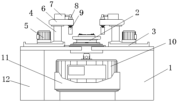
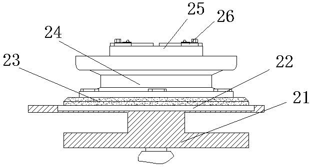
[0017] see Figure 1-2 , the present invention provides a technical solution:

[0018] A tooth groove finish machining device for gears, comprising a working table 1 and a gear fixing table 2, the gear fixing table 2 is installed in the middle of the top of the working table 1, and a guide plate 3 is installed on both sides of the gear fixing table 2, and the guide plate 3 The inner side of the vertical column 4 is slidingly installed with a column 4, and the...


PUM


Abstract

The invention discloses a finish machining device of the tooth grooves of gears. The finish machining device comprises a workbench and a gear fixing table. The gear fixing table is mounted in the middle of the top of the workbench. Guide plates are mounted on two sides of the gear fixing table. A standing column is slidably mounted on the inner side of each guide plate. A guide drive motor is mounted on the outer side of the bottom of each standing column. A bearing bar is further mounted at the top of each standing column. A pneumatic valve is mounted at the top of each bearing bar. A pneumatic telescopic column is mounted in the inner cavity in one end, close to the gear fixing table, of each bearing bar. A polishing column is mounted at the bottom end of each pneumatic telescopic column. A motor support is mounted at the bottom of the inner cavity of the workbench. A rotating motor is mounted at the top of the motor support. Compared with the traditional manual polishing technology, the finish machining device has the advantages that the device is accurate in tooth groove polishing depth, small in size, simple to operate, fast in machining, high in efficiency and suitable for large-scale gear production.

Description

technical field [0001] The invention relates to the technical field of gear finishing, in particular to a gear tooth groove finishing device. Background technique [0002] During the production process of gears, the tooth grooves on the gears will leave some scratches or cuts in the tooth grooves after the gear shaping machine cuts the grooves, which makes the inner side of the tooth grooves uneven and affects the smoothness of the gear rotation. It is easy to greatly increase the wear intensity between the gears and shorten the service life of the gears. Therefore, after the gears are cut or shaped, the tooth grooves of the gears are usually polished. Grinding process, most of them are done by manually controlling the grinding machine. Manual semi-automatic grinding is used. The depth of tooth groove grinding is completely judged by the experience of the operator. It has high requirements, which brings inconvenience to the personnel management of the enterprise. In additio...

Claims


Application Information

Patent Timeline
Patent Type & Authority Patents(China)
IPC IPC(8): B23F19/00B23F23/06B23F23/12
CPCB23F19/00B23F23/06B23F23/1237
Inventor 李健
Owner 重庆市綦江区余诚齿轮有限公司
Learn More