
Semiconductor device with channel stopper and method for producing the same

一种沟道截断、半导体的技术,应用在半导体器件、半导体/固态器件制造、半导体/固态器件零部件等方向

Active Publication Date: 2016-10-12
INFINEON TECH AG
View PDF4 Cites 7 Cited by
  • Summary
  • Abstract
  • Description
  • Claims
  • Application Information

AI Technical Summary

Problems solved by technology

There is no known way to effectively suppress this parasitic effect in conjunction with the p-type channel stopper ring

Method used


Image

  • Semiconductor device with channel stopper and method for producing the same
  • Semiconductor device with channel stopper and method for producing the same
  • Semiconductor device with channel stopper and method for producing the same

Examples


Embodiment Construction

[0015] In the following detailed description, reference is made to the accompanying drawings, which form a part of this detailed description, and in which are shown by way of illustrations specific embodiments in which the invention may be practiced. In this regard, directional terms, such as "top," "bottom," "front," "rear," "front," "tail," "lateral," "vertical," etc., are described with reference to or multiple graph orientations to use. These terms are intended to encompass different orientations of the device in addition to orientations other than those depicted in the figures. Since components of an embodiment may be positioned in many different orientations, directional terms are used for purposes of illustration and are in no way limiting. In addition, terms such as "first", "second", etc. are also used to describe various elements, regions, sections, etc., and these terms are also not intended to be limiting. Throughout the description, similar terms refer to simila...


PUM


Abstract

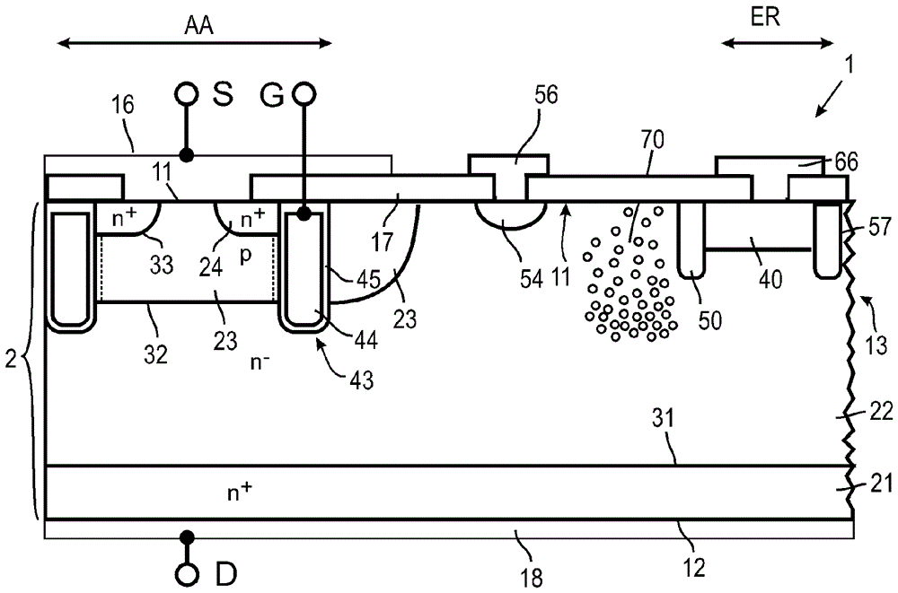
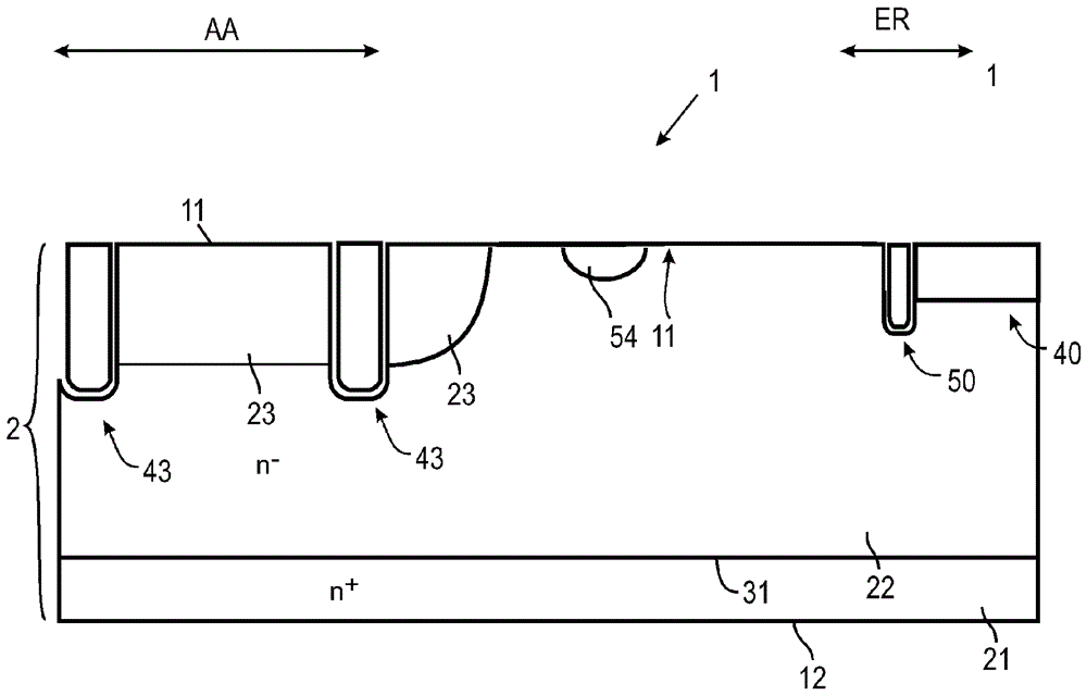
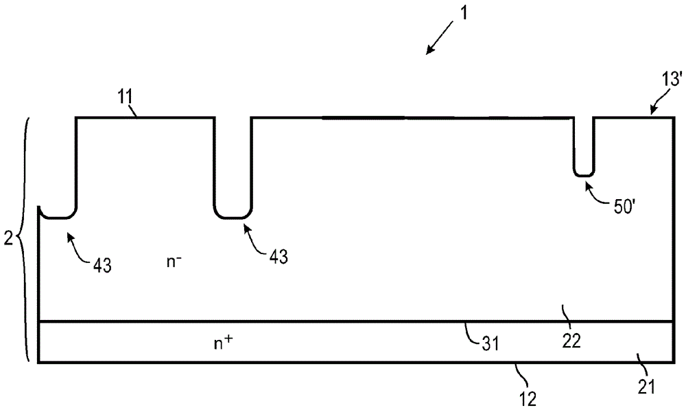
The invention relates to a semiconductor device with a channel stopper and a method for producing the same. A vertical semiconductor device (1) comprises a substrate (2) having a front surface (11) and a back surface (12), an active area (AA) located in the substrate (2), having a drift region (22) doped with a first dopant type, an edge termination region (ER) laterally surrounding the active area (AA), a channel stopper terminal (40) provided at the front surface and located in the edge termination region (ER), and a first suppression trench (50) located on a side of the channel stopper terminal (40) towards the active region (AA), and provided adjacent to the channel stopper terminal (40). Further, a production method for such a semiconductor device is provided.

Description

technical field [0001] The present disclosure relates to embodiments of semiconductor devices having channel stop rings, and in particular to unipolar and bipolar power semiconductor devices such as field effect transistors (FETs) and insulated gate bipolar transistors (IGBTs) having channel stop rings. ) and integrated circuit embodiments. Background technique [0002] In power FET devices, channel stop rings are used to suppress the potential establishment of parasitic inversion channels in the edge regions of the chip. The channel stop ring generally includes a doped region close to the edge region of the chip, which is hereafter referred to as the channel stop ring terminal. The latter is electrically connected to the back or drain potential of the device. On the surface adjacent to the trench stopper ring terminals, there is typically provided a field plate comprising metal (for example aluminum) or another conductive material, which is part of the trench stopper ring...

Claims


Application Information

Patent Timeline
Patent Type & Authority Applications(China)
IPC IPC(8): H01L29/06H01L23/58H01L29/78H01L29/739H01L21/331H01L21/336
CPCH01L23/58H01L29/0638H01L29/66348H01L29/66666H01L29/7397H01L29/7398H01L29/7827H01L29/7811H01L29/7813H01L29/407H01L29/7395H01L29/0619H01L29/0878H01L29/1095H01L21/761H01L29/0623
Inventor E.法尔克F.D.普菲尔施H-J.舒尔策S.福斯
Owner INFINEON TECH AG
Learn More