Method and apparatus for changing laser beam into rectangular scanning light screen

A rectangular scanning and laser beam technology, applied in optics, optical components, instruments, etc., can solve the problems of high energy density in the middle of the scanning beam, bending of the scanning light, and uneven energy distribution of the scanning beam, so as to improve the practical range, size and Effects of reduced power consumption and uniform energy

Active Publication Date: 2016-10-12
苏州小优智能科技有限公司
View PDF3 Cites 4 Cited by
  • Summary
  • Abstract
  • Description
  • Claims
  • Application Information

AI Technical Summary

Problems solved by technology

At the same time, it solves the two major problems of the traditional single cylinder lens optical scanning module: one is that the energy distribution of the scanning beam is uneven, and the scanning beam presents a situation where the energy density in the middle is high and the two sides are low; the other is that the light moves to When the angle of incidence is not normal, the scanning light is bent on both sides

Method used


Image

  • Method and apparatus for changing laser beam into rectangular scanning light screen
  • Method and apparatus for changing laser beam into rectangular scanning light screen
  • Method and apparatus for changing laser beam into rectangular scanning light screen

Examples


Embodiment 1

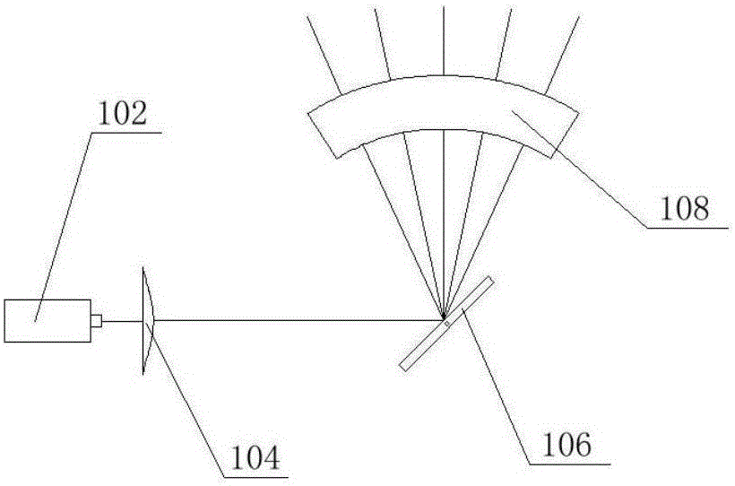
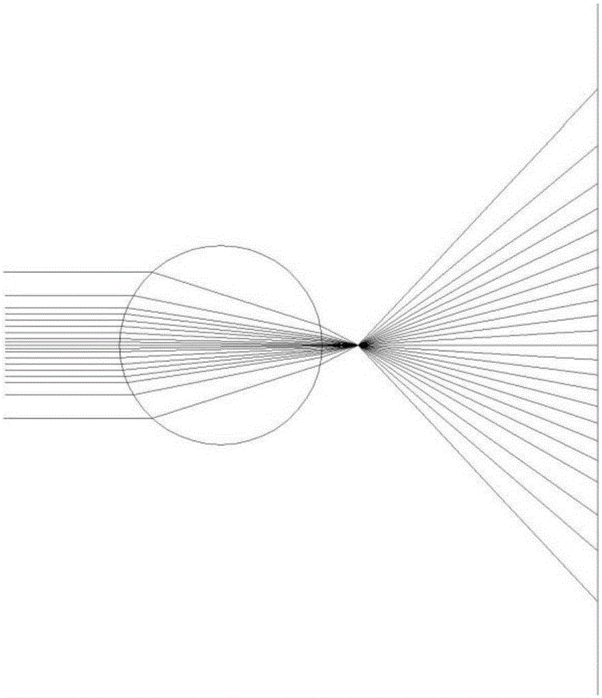
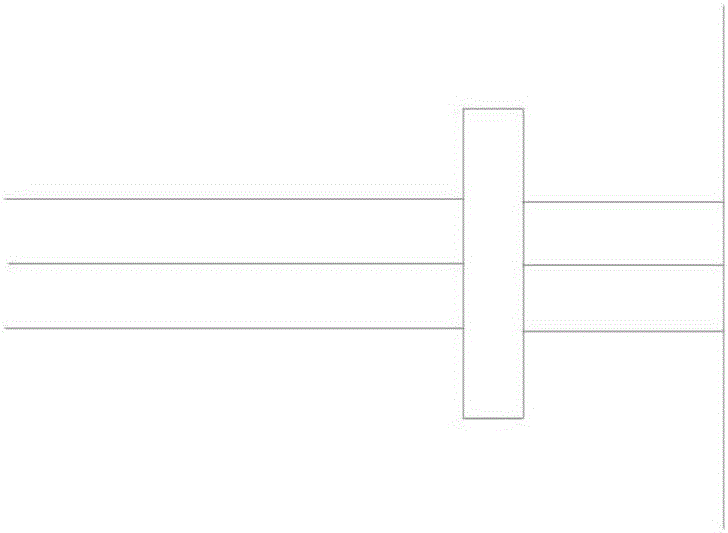
[0033] A method of changing the laser beam into a rectangular scanning light curtain. The scattered laser beam generated by the laser is modulated by the beam energy through the converging lens, modulated into a parallel beam with high energy distribution in the middle part and weak edge distribution, and projects it on the scanning galvanometer Above, under the control of the control system, the scanning galvanometer rotates to reflect the light beam into a narrow scanning beam. The scanning beam is scattered into a wide rectangular scanning light curtain by the scattering lens, and the scanning galvanometer is twisted by the control system. And the control of the laser power, within one scan period of the scanning galvanometer, adjust the brightness of different strip areas in the rectangular light curtain area.

[0034] The scattering lens is a curved cylindrical lens. The longitudinal section of the scattering lens is a section of a ring. The center of the ring is located o...

Embodiment 2

[0056] Including the principle in Embodiment 1, in order to ensure the outer product shape of the device, reflectors can be added in the middle of some components to change the direction of the light beam, so as to change the position of the components.

Embodiment 3

[0058] Including the gist of Embodiment 2, the control system 110 can be outside the device and integrated with the final product.


PUM


Abstract

The invention, which belongs to the field of the photoelectric technology, discloses a method and apparatus for changing a laser beam into a rectangular scanning light screen. According to the technical scheme, light beam energy modulation is carried out on a scattered laser beam generated by a laser by a convergence lens and the laser beam is modulated into a parallel beam with the middle part with high energy distribution and edges with low energy distribution; the changed parallel beam is projected on a scanning galvanometer; under control by a control system, the scanning galvanometer makes twisting motion and reflects the light beam into a narrow scanning beam; and the scanning beam is processed by a scattering lens to form a wide rectangular scanning light screen. The method and apparatus have the following beneficial effects: because of the specific optical lens, the laser beam emitted by the laser can be shaped into the rectangular scanning light screen and the outputted scanning light screen has the uniform energy, so that a phenomenon the two sides of the non-vertical-incidence-angle scanning light are bent can be avoided.

Description

technical field [0001] The invention belongs to the field of optoelectronic technology, and in particular relates to a method and a device for changing a laser beam into a rectangular scanning light curtain. Background technique [0002] It is a commonly used 3D scanning imaging technology to irradiate a specific pattern on the object to be measured, and then calculate the distance information of the object surface by photographing the pattern modulated by the object surface. Irradiation pattern is an important technology in 3D scanning imaging, and it is the limiting factor of 3D scanning imaging quality. The laser light curtain lighting device based on the scanning galvanometer can realize a high-quality adjustable light curtain, and can save a lot of volume and weight. There are two major problems with the single cylinder lens optical scanning module used in traditional technology: one is that the energy distribution of the scanning beam is uneven, and the scanning beam ...

Claims


Application Information

Patent Timeline
Patent Type & Authority Applications(China)
IPC IPC(8): G02B26/10G02B27/09
CPCG02B26/105G02B27/0955
Inventor 杜先鹏丁大海郭俊兴代启强
Owner 苏州小优智能科技有限公司
Why Eureka
Try Eureka