
Micro-lens (or micro-lens array) imaging detection plate

A microlens array, imaging detection technology, applied in the optical field, to achieve the effect of simple and fast detection process

Active Publication Date: 2016-10-12
JINAN UNIVERSITY
View PDF5 Cites 8 Cited by
  • Summary
  • Abstract
  • Description
  • Claims
  • Application Information

AI Technical Summary

Problems solved by technology

[0003] Existing refractive index measurement techniques such as Abbe refractometers cannot monitor the transient changes of the refractive index of local micro-regions of the solution over time in real time without disturbing the sample solution.

Method used


Image

  • Micro-lens (or micro-lens array) imaging detection plate
  • Micro-lens (or micro-lens array) imaging detection plate
  • Micro-lens (or micro-lens array) imaging detection plate

Examples


Embodiment 1

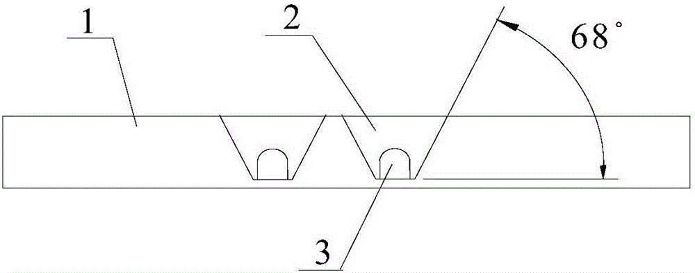
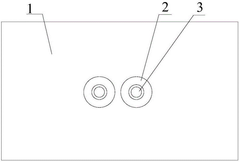
[0033] Such as Figure 1a and Figure 1b As shown, an imaging detection plate with two microlenses can detect two samples at the same time. The thickness of the transparent plate 1 of the entire imaging detection plate is 3.5 mm, and the thickness of the bottom of the trapezoidal concave hole 2 is 0.25 mm. Two cylindrical microlenses 3 in a trapezoidal concave hole 2 have a radius of 0.5 mm and a height of 1.0 mm; the two cylindrical microlenses 3 and the transparent plate 1 with two holes are integrally formed by precision injection molding of PMMA plexiglass material And made, its transparency > 90%, smoothness 40; use the multifunctional hydrophilic treatment agent DP-9993 that is composed of polyester-polyether-organic silicon terpolymer to carry out hydrophilic treatment (soaking at room temperature for 24 hours) .

[0034] When using this dual microlens imaging detection plate for solution refractive index detection, the solution to be measured is injected into the two ...

Embodiment 2

[0037] Different from embodiment 1, the cylindrical microlens 3 of the microlens imaging detection plate in embodiment 2 is a glass microlens, which is glued in the trapezoidal concave hole 2, and it is characterized in that the radius of the cylindrical microlens is 0.375 mm, height is 0.85 mm; transparent plate 1 is a PMMA plexiglass plate, thickness is 3 mm, the thickness at the bottom of the trapezoidal concave hole 2 is the same as the parameters in embodiment 1, and the process of other processing and detection imaging is the same as in embodiment 1.

Embodiment 3

[0039] Different from Embodiment 1, the microlens imaging detection plate in Embodiment 3 has 16 microlenses, which form a 4×4 array, such as Figure 3a and Figure 3b As shown, 16 cylindrical microlenses 3 are respectively placed in 16 trapezoidal concave holes 2, the thickness of the transparent plate 1 of the microlens array imaging detection plate is 3 millimeters, the radius of the cylindrical microlenses 3 is 0.5 millimeters, and the height is 1.5 millimeters , the cylindrical microlens 3 and the porous transparent plate 1 are made of PMMA plexiglass material through precision injection molding as a whole, with a transparency of >90%, a smoothness of 40, and a thickness of the bottom of the trapezoidal concave hole of 0.25 mm. Other processing and imaging detection processes are the same as in Example 1, except that the detection board can detect 16 samples at the same time.


PUM


Abstract

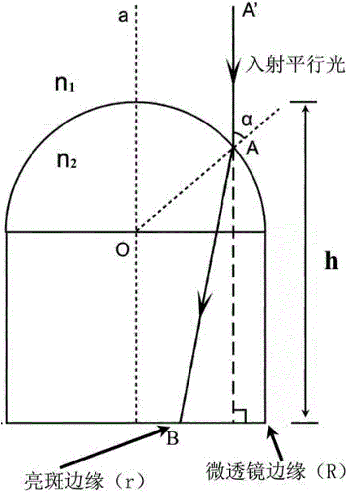
The invention discloses a micro-lens (or micro-lens array) imaging detection plate which comprises a transparent plate with the thickness of 3-5 mm. One or more trapezoid concave holes are formed in the plate surface, and a columnar micro-lens with a hemisphere at the upper portion and a cylinder the lower portion is arranged in each trapezoid concave hole and is formed by PMMA organic glass material and the transparent plate with the trapezoid concave holes together through precision injection molding. The imaging characteristic of the columnar micro-lenses of the micro-lens (or micro-lens array) imaging detection plate is that when the trapezoid concave holes of the transparent plate are filled with liquid or other media to immerse the columnar micro-lenses, and images of the columnar micro-lenses are round images with the outer edges which are black rings under parallel light exposure due to the refraction effect of light; the outer radiuses R of the black rings are the radiuses of the columnar micro-lenses, the inner radiuses r of the black rings are the refractive index n1 of the immersion liquid, the refractive index n2 of the columnar micro-lenses and the heights h of the columnar micro-lenses form a theoretical relation, and the real-time refractive index of the liquid or the medium can be determined by utilizing the plate to monitor values of the inner radiuses r of the black rings.

Description

technical field [0001] The invention belongs to the field of optical technology, and relates to an optical detection device, in particular to a microlens (or microlens array) imaging detection plate. Background technique [0002] The refractive index of a solution or medium is a very important optical characteristic, and it is also a function of the solution concentration, temperature, etc., so monitoring the real-time change of the refractive index of the solution plays an important role. Especially in many antigen-antibody solutions, when the antigen-antibody reaction occurs, the refractive index of the solution will change with time according to a certain rule. Therefore, by monitoring the refractive index change of the antigen-antibody solution before and after the reaction, the measured The amount of antigen or antibody in a sample. However, this kind of determination has high requirements on the refractive index measurement technology. First, it cannot interfere with ...

Claims


Application Information

Patent Timeline
Patent Type & Authority Applications(China)
IPC IPC(8): G01N21/41
CPCG01N21/41G01N2201/0638G01N21/0303G01N21/253G01N2021/0307G01N2021/0382G01N21/4133G01N2201/0639G02B3/0056G01N21/431G02B13/0055
Inventor 黄耀熊何江
Owner JINAN UNIVERSITY
Learn More